5.
6.
7.
8.
INSTALLATION
OF A
SECOND
RECETVER
To connect
a second
receiver, it
is
necessary to run
a coaxial line
from
the AUX
RCVR auto
radio-type
jack,
on
the rear of
the PT,
to the receiver.
An
auto
audio-
type
plug
is
supplied
with the PT,
and
a coaxial
cable of the
RG58/U
type should
be i nstal
led as
fol
lows:
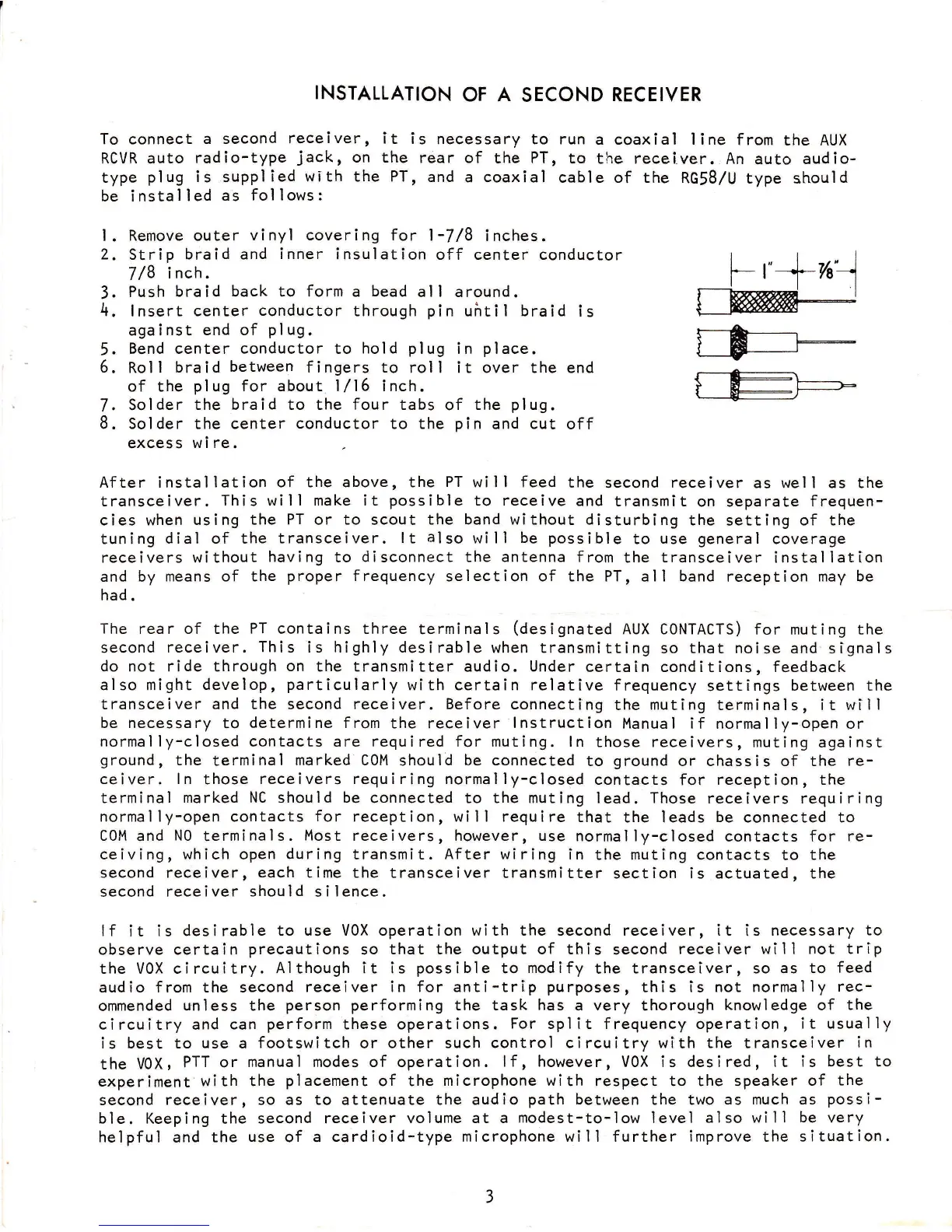
l.
Remove
outer
vinyl covering for
1-7/8
inches.
2,
Strip
braid and
inner
insulation
off center conductor
7 /8
i nch.
3.
Push
braid back to form a
bead
all around.
4.
lnsert
center
conductor
through
pin
ufitil
braid
is
aga i
nst end of
pl
ug.
Bend center conductor to
hold
plug
in
place.
Roll
braid
between
fingers to
roll it over the end
of the
plug
for
about
l/15 inch.
Solder
the braid to the four tabs
of
the
plug.
Solder
the
center
conductor
to the
pin
and
cut
off
excess wi
re.
After installation
of the above, the
PT
will feed
the
second
receiver
as well as the
transceiver.
This will make it
possible
to receive
and
transmit
on separate
frequen-
cies when
using the
PT
or
to
scout
the band without disturbing
the
setting
of the
tuning
dial of the
transceiver. lt
also
will
be possible
to
use
general
coverage
receivers
without
having
to
disconnect
the
antenna
from
the
transceiver
installation
and by
means of the
proper
frequency
selection of the
PT, all
band
reception may
be
had.
The
rear of the PT contains three
terminals
(designated
AUX
CONTACTS) for
muting
the
second
receiver.
This
is highly desirable
when transmitting
so that
noise
and slgnals
do not ride through
on
the transmitter
audio.
Under
certain
conditions, feedback
also might
develop,
particularly
with
certain
relative
frequency
settings
between the
transceiver and
the
second
receiver. Before
connecting
the
muting
terminals, it will
be necessary
to
determine
from
the receiver
lnstruction
Manual
if
normally-open or
normally-closed contacts
are required for muting. ln
those receivers,
muting against
ground,
the
terminal
marked COM
should
be connected
to
ground
or chassis of the re-
ceiver.
ln
those
receivers requiring normally-closed
contacts
for
reception, the
terminal
marked
NC
should
be
connected to the muting
Iead.
Those
receivers requiring
normally-open contacts
for
reception, will require
that
the leads
be
connected to
COM
and
N0
terminals.
Most
receivers, however, use
normally-closed
contacts for
re-
ceiving, which open
during
transmit.
After
wiring in
the muting contacts
to
the
second receiver, each time the
transceiver transmitter
section is actuated, the
second receiver
should
si
lence.
lf
it
is desirable
to use VOX operation with the second
receiver,
it
is
necessary
to
observe certain
precautions
so
that the output of this
second
receiver
will not trip
the VOX circuitry.
Although it is
possible
to
modify
the
transceiver, so as to
feed
audio from the second
receiver in for anti-trip
purposes,
this
is not normally
rec-
ommended
unless the
person
performing
the task has a
very thorough
knowledge
of
the
circuitry and
can
perform
these operations.
For
split frequency operation,
it usually
is best
to
use a
footswitch
or other
such control circuitry with the
transceiver
in
the
V6X,
PTT or
manual modes of
operation.
lf, however,
VOX is desired,
it
is
best to
experiment with
the
placement
of the
microphone with
respect to the speaker
of
the
second
receiver,
so
as to attenuate the audio
path
between
the two as
much as
possi-
ble.
Keeping the
second receiver
volume at a
modest-to-low
level
also will
be
very
helpful
and the
use of a
cardioid-type microphone will further improve the situation.
 Loading...