American Flame AFVK-SP Valve Kits
REV. 10-8-19 Page 2
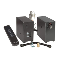
DESCRIPTION: This installation manual covers three valve kits; AFVK-SP, AFVK-SP-HL and AFVK-SP-MHL.
Installation is the same for all of the kits however the operation is slightly different. All valve kits are re tested at the
factory to ensure proper operation. Each kit is supplied with a individual rocker switch to enable ON/OFF operation
without the transmitter (if needed) and the ability to have continuous pilot or intermittent pilot ignition (IPI), which only
operates the pilot when the log set is turned ON. See each kit below and their contents.
Table of Contents
Description & Contents Page 2
Valve Kit Models Page 3
Installing into a Pre-Existing Log Set Page 4
Installing with a New Log Set Page 5
Reference Section & Wiring Diagram Page 6
Battery Pack Preparation Page 7
Gas Conversion Page 8
Operation of System Page 9-10
Troubleshooting Page11
Replacement Parts Page 12
Warranty Page12
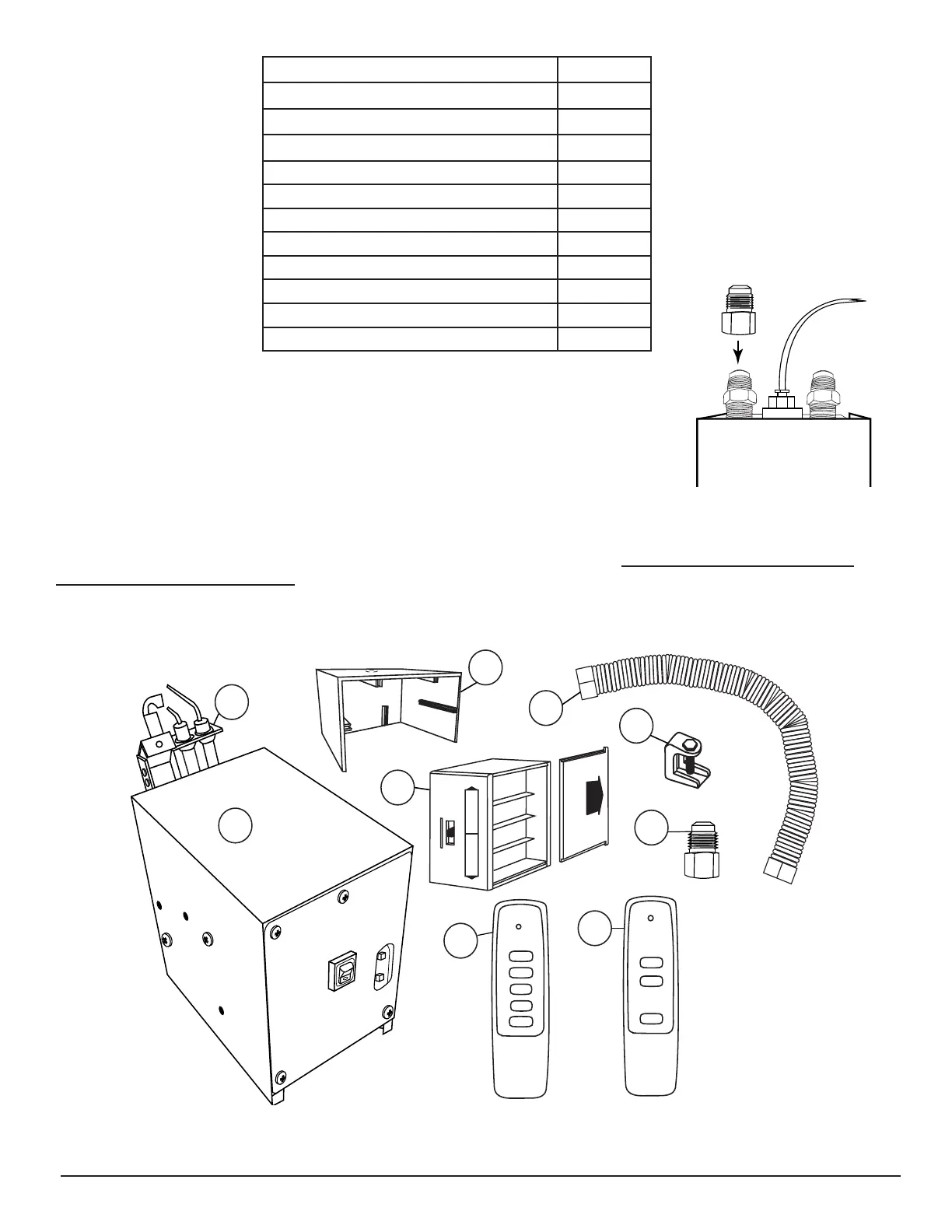
INSTALLER: Each valve kit is supplied with a (UR3-68) adapter that provides an option
to convert the inlet or outlet gas connection from 3/8" are tting to a 1/2" ared tting.
Simply thread the UR3-68 on to the inlet/outlet gas ared tting as shown in Fig. 1.
Note: No pipe joint compound or thread tape is necessary. Ensure ttings are tight and
test for gas leaks.
Top View
(Back of Valve)
I
n
l
e
t
UR3-68
Fig. 1 Installing UR3-68 to the
inlet or outlet side of gas valve
ON
OFF
HI
LO
PILOT
Continuous
Latching Solenoid DC Motor Drive
ON
ON/OFF
Continuous Pilot
OFF
1
2
3
4
5
6
7
8
9
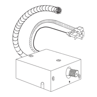
Fig. 2 Carton contents: 1- Valve Kit 2- Pilot Assembly 3- Battery Pack Heat Shield 4- Battery Pack
5- Flex Connector 6- Damper Clamp 7- Adapter Fitting 8- SP1001HL 9- SP1001