Reading the Floor Plan
Two floor plans are included with the unit. One will be located in the accessory box and the other will be
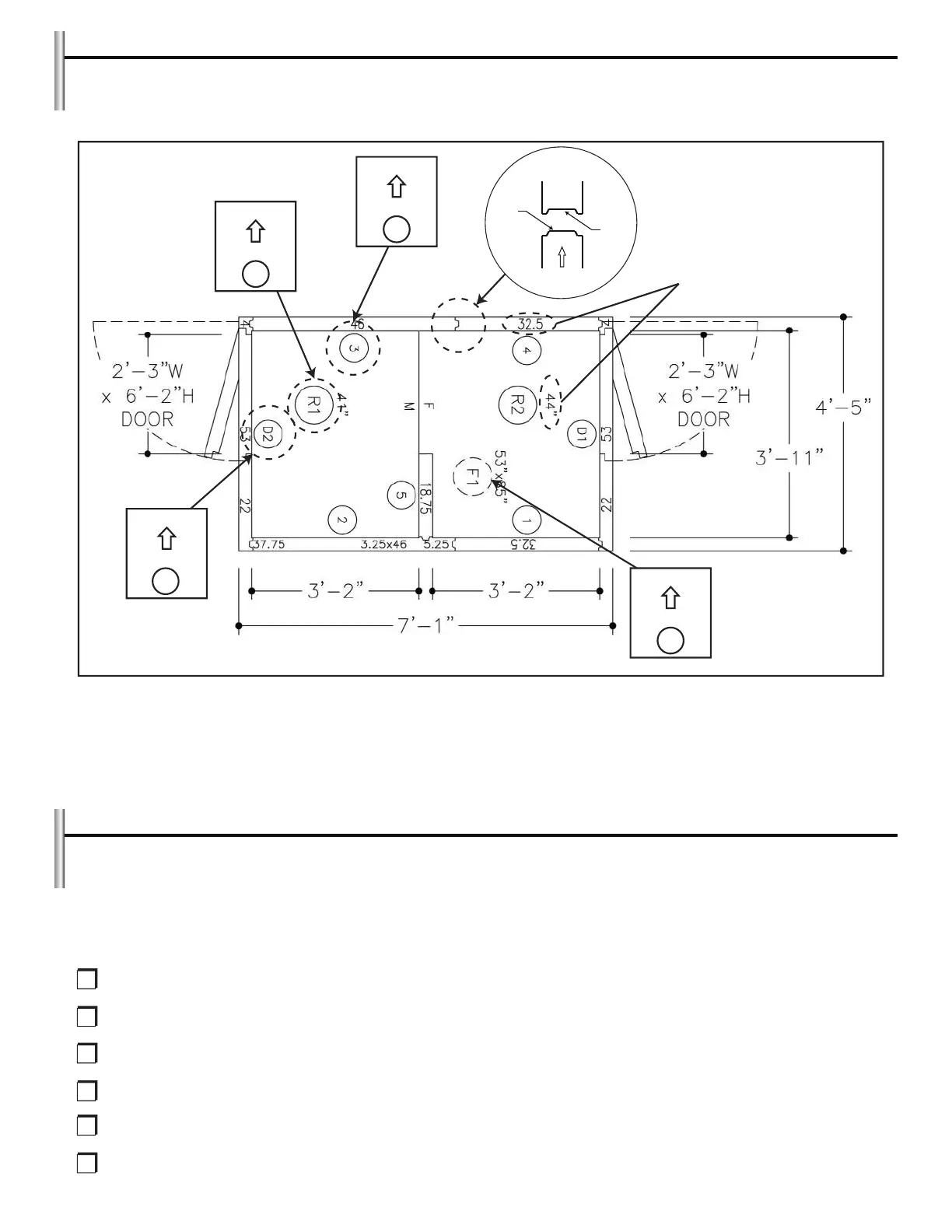
attached to the exterior door and frame assembly. Below is a sample floor plan.
UP
WALL PANEL
3
UP
ROOF PANEL
R1
UP
DOOR PANEL
D2
UP
FLOOR PANEL
F1
FEMALE
ROUT
MALE
ROUT
INDICATES PANEL WIDTH
A review of the floor plan will indicate all dimensions, as well as all wall, ceiling floor and door locations. All
wall, ceiling, floor and door/frame sections are numbered on the floor plan as well as on the corresponding
equipment. All wall panels will have an arrow indicating which edge of the panel should be up. The floor plan
is designed to help you easily and systematically install all components of the cabinet. For ease of installation
always start with wall panel number one.
Preparing the Installation Site
An overall inspection should be done of the installation area to familiarize oneself with potential problems
such as building walls, ceilings, floors or concrete slabs. These items need to be considered when preparing
the site. It is critical that the unit fits properly into the space provided.
PLEASE REVIEW THE FOLLOWING IN PREPARATION FOR INSTALLING THE UNIT:
Note any offsets for building columns.
Check condition of floor or slab (clean, smooth and level).
Check height restrictions (ceiling, beams, duct work, lights, piping, etc.).
Check location of floor drains and condensate lines.
Check compliance with all building, electrical and mechanical codes.
Verify that the door will open without restriction and does not obstruct frequent traffic patterns. The
door should swing away from traffic flow when possible.
4
 Loading...