Do you have a question about the American Standard 4A7A7 and is the answer not in the manual?
Table detailing the physical dimensions and weight for various unit models.
Specifies maximum total length and vertical change for refrigerant lines.
Guidance on positioning the unit for optimal performance and avoiding issues.
Precautions for units installed in areas with snow or freezing temperatures.
Requirement for Seacoast Salt Shields in coastal environments.
Steps to check for damage and remove the unit from its pallet.
Guidelines for installing the unit on a support pad, ensuring levelness and drainage.
Table detailing line sizes and connection sizes for different unit models.
Information on the factory refrigerant charge and when adjustments are needed.
Guidance on determining required line length and lift measurements for system.
Importance of insulating the vapor line and avoiding metal contact.
Precautions when reusing existing refrigerant lines for retrofit applications.
Guidelines to prevent noise transmission and ensure proper line routing.
Step-by-step instructions for properly brazing refrigerant lines.
Procedure for pressurizing lines with nitrogen and checking for leaks.
Steps for evacuating the system using a micron gauge to remove moisture.
Procedure for opening the gas service valve after evacuation.
Procedure for opening the liquid service valve with extreme caution.
Table defining maximum total length for low voltage wiring based on wire size.
Wiring diagrams for connecting thermostat, air handler, and outdoor unit.
Guidance on matching high voltage power supply to equipment nameplate and codes.
Recommendation to install a separate disconnect switch at the outdoor unit.
Requirement to ground the outdoor unit per national, state, and local codes.
Step-by-step procedure for safely starting up the system after installation.
Instructions for checking outdoor and indoor temperatures for accurate charging.
Method for adjusting system charge using subcooling above 55°F outdoor temp.
Recommended method for charging systems below 55°F outdoor temperature.
Final inspection list and procedures to ensure proper unit operation.
Table listing system faults, primary/secondary causes, and checks.
This document serves as an installer's guide for American Standard 4A7A7 series condensing units, providing comprehensive instructions for installation, startup, and maintenance. It emphasizes compliance with national, state, and local codes throughout all phases of the installation process. The guide is intended for individuals with adequate electrical and mechanical experience, highlighting the importance of proper handling and safety precautions.
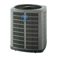
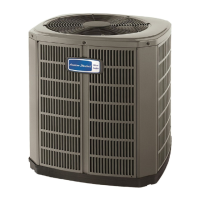
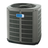
The American Standard 4A7A7 condensing units are designed to be part of a central air conditioning system. These outdoor units work in conjunction with an indoor evaporative coil to provide cooling for a building. They are factory charged with R-410A refrigerant, a high-pressure refrigerant that requires specific handling procedures and approved service equipment. The units are designed for optimal performance and efficiency when installed as part of approved matched indoor and outdoor systems, as rated by AHRI. The system's primary function is to transfer heat from the indoor environment to the outdoors, thereby cooling the conditioned space. The guide details the necessary steps to ensure the unit is properly integrated into the overall HVAC system, including refrigerant line connections, electrical wiring, and system charging.
The installation process begins with unit preparation, including checking for shipping damage and carefully removing the unit from its pallet. Proper unit placement is crucial, with considerations for roof mounting, sound and vibration isolation, and adequate clearances from walls and shrubbery to ensure optimal airflow and service access. For cold climates, specific recommendations are provided, such as elevating the unit to allow for snow and ice drainage and installing snow drift barriers.
Refrigerant line considerations are extensively covered, including maximum total line lengths and vertical lift limits. The guide provides tables for standard and alternate line sizes, as well as service valve connection sizes, to ensure proper system operation. It stresses the importance of insulating the vapor line and preventing direct metal-to-metal contact between the liquid and vapor lines. For retrofit applications, precautions are outlined for reusing existing refrigerant lines, emphasizing the need to verify correct sizing and ensure the lines are free of leaks, acid, and oil.
Refrigerant line routing instructions focus on preventing noise transmission within the building structure. This includes using isolation hangers when fastening lines to structural elements and insulating lines that pass through walls or sills. Minimizing 90-degree turns and isolating lines from ductwork are also recommended.
Brazing the refrigerant lines is a critical step, with detailed instructions provided for deburring and cleaning pipe ends, purging with dry nitrogen, and protecting valve bodies from heat damage using wet rags. The guide also specifies the correct installation of a field-installed external drier in the liquid line, ensuring proper refrigerant flow direction. After brazing, a leak check is performed by pressurizing the system with dry nitrogen and checking for bubbles at all brazed locations.
Evacuation of the refrigerant lines and indoor coil is essential to remove non-condensable gases and moisture. The process involves evacuating the system until a micron gauge reads no higher than 350 microns, followed by observing the gauge to ensure it does not rise above 500 microns within one minute, indicating a successful evacuation.
Opening the service valves is a precise procedure. The guide provides clear instructions for removing valve stem caps, turning the valve stems to the fully open position, and replacing the caps to prevent leaks. Extreme caution is advised when opening the liquid line service valve to avoid abrupt release of system charge.
Electrical connections are divided into low voltage and high voltage sections. Low voltage wiring guidelines specify maximum wire lengths based on wire gauge to ensure proper communication between the outdoor unit, indoor unit, and thermostat. High voltage instructions emphasize grounding the outdoor unit according to codes and installing a separate disconnect switch. Wiring diagrams are referenced for specific connection details.
The guide outlines a systematic startup procedure, beginning with ensuring all previous installation steps are completed. This includes setting the system thermostat to OFF, applying power to the units, and waiting for a specified period (one hour if a crankcase heater is used and ambient temperature is below 70°F) before starting the unit.
System charge adjustment is a key maintenance feature, with two primary methods described: subcooling charging for outdoor temperatures above 55°F and weigh-in method for temperatures below 55°F.
For subcooling charging, installers use charts to determine the final subcooling value based on total line length and vertical lift. They then measure the liquid line temperature and pressure at the outdoor unit's service valve and compare these readings to a refrigerant charging chart (Table 14.2) to determine if refrigerant needs to be added or recovered. The system must be stabilized by operating for a minimum of 20 minutes before making accurate measurements and adjustments.
The weigh-in method for charging at lower outdoor temperatures involves calculating the additional refrigerant needed based on the length of interconnecting tubing beyond the factory-charged 15 feet. A charge multiplier (0.6 oz/ft) is used to determine the exact amount of refrigerant to add prior to opening the service valves. This method is also suitable for initial installations or when replacing the system charge.
Finally, the guide includes a comprehensive checkout procedure to verify proper system operation. This checklist covers items such as leak checking refrigerant lines, proper insulation, securing and isolating lines, sealing masonry passages, verifying electrical connections, observing outdoor fan operation, ensuring free drainage of the indoor coil drain line, checking supply registers and return grilles, confirming filter installation, and verifying correct airflow settings. The system should be operated in each mode to ensure safe and efficient performance. The guide also includes a troubleshooting section with a detailed table of system faults, their primary and secondary causes, and the mode in which they typically occur, aiding in diagnosing and resolving common issues.
| Refrigerant | R-410A |
|---|---|
| Phase | 1 |
| Dimensions (Outdoor Unit) | Varies by model |
| Weight (Outdoor Unit) | Varies by model |
| Type | Air Conditioner |
| HSPF Rating | Not Applicable |
| Energy Efficiency | High |
| Stages | Single Stage |
| Cooling Capacity (BTU/h) | 24, 000 - 60, 000 |
| Heating Capacity (BTU/h) | Not Applicable |
| Sound Level (Outdoor) | 76 dB |
| Voltage | 208/230V |
| Dimensions (Indoor Unit) | Varies by model |
| Weight (Indoor Unit) | Varies by model |