EasyManua.ls Logo

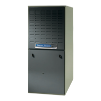
American Standard AUXIB060A9361A User Manual

American Standard AUXIB060A9361A
32 pages
To Next Page IconTo Next Page
Page #1 background imageLoading...
Page #1 background image
IIIIII IIIIIIIIIIIIII IIII IIII
18- CD19D6- 27
*DX-IN-IO
Upflow / Horizontal and Downflow / Horizontal
Gas-Fired, Direct Vent Condensing Furnaces
*UXIB040A9241A *UXIC100A9481A
*UXIB060A9361A *UXID100A9601A
*UXIB080A9421A *UXID120A9601A
*UXIC080A9601A
*__First letter may be "A" or "T"
ALL phases of this installation must comply with NATIONAL, STATE AND LOCAL CODES
*DXIB040A9241A
*DXIB060A9361A
*DXIB080A9421A
*DXIC100A9481A
*DXID120A9601A
IMPORTANT -- This Document is customer property and is to remain with this unit.
Please return to service information pack upon completion of work.
*UX-1 *DX-1
A/R
FLOW
UPFLOW
DOWNFLOW
AIR
FLOW
AIR
FLOW
/
UPFLOW/HORIZONTAL
\
DOWN FLOW/HORIZONTAL FLOW
o
A341624P06
Question and Answer IconNeed help?

Do you have a question about the American Standard AUXIB060A9361A and is the answer not in the manual?

American Standard AUXIB060A9361A Specifications

General IconGeneral
ModelAUXIB060A9361A
TypeGas Furnace
Blower MotorVariable Speed
Fuel TypeNatural Gas
AFUE96%
StagesSingle Stage
BTU Input60, 000 BTU
Efficiency Rating96%
Heating Capacity60, 000 BTU/h

Summary

SAFETY SECTION

CARBON MONOXIDE POISONING HAZARD

Failure to follow venting steps can lead to carbon monoxide poisoning or death.

FIRE OR EXPLOSION HAZARD

Failure to follow warnings can result in serious injury, death, or property damage.

GENERAL INSTALLATION INSTRUCTIONS

CAUTIONS FOR INSTALLATION

Warnings regarding use as a construction heater and corrosive atmospheres.

UPFLOW INSTALLATION

DOWNFLOW INSTALLATIONS

AIR FOR COMBUSTION AND VENTILATION

DUCT CONNECTIONS

GENERAL VENTING

CONDENSATE DRAIN INSTRUCTIONS

FIELD WIRING DIAGRAMS

1 STAGE HEATING (NO COOLING)

Wiring diagram for single-stage heating without cooling.

1 STAGE HEATING, 1 STAGE COOLING

Wiring diagram for single-stage heating and cooling.

ELECTRICAL CONNECTIONS

GAS PIPING

COMBUSTION AND INPUT CHECK

START UP AND ADJUSTMENT

CONTROL AND SAFETY SWITCH ADJUSTMENTS

ABNORMAL CONDITIONS

EXCESSIVE COMBUSTION PRESSURE (WIND IN EXCESS OF 40 M.P.H.) VENT OR FLUE BLOCKAGE

Troubleshooting for high combustion pressure due to venting issues.

LOSS OF FLAME

Steps to take if the flame is lost during operation.

INTEGRATED FURNACE CONTROL ERROR FLASH CODES

Related product manuals