A
April WardAug 22, 2025
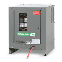
Why does my AMETEK/PRESTOLITE POWER ULTRA CHARGE Battery Charger smell hot?
- JJackie GrahamAug 22, 2025
If your AMETEK/PRESTOLITE POWER Battery Charger smells hot, it could be due to several reasons: * Inadequate ventilation. * Ambient temperature being too high. * Lack of maintenance. * A bad transformer or control transformer. * A bad internal power connection. * A bad control board or inductor. * The wrong amp/hour jumper is installed. * A bad expansion board.