6
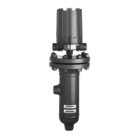
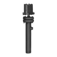
46-635 External Cage Displacer Actuated Liquid Level Switches
Internal Circuit
(Right) Switch
1
2
3
Load
Load
Close on high level
Common
Close on low level
Line
4
5
6
Internal Circuit
(Left) Switch
Load
Load
Close on high level
Common
Close on low level
Line
Figure 4
Housing Set Screws
Figure 5
Terminal Connections
DPDT Switch Mechanism
Series B, C, D, F and 8
2.4 Mounting
Caution: This instrument is intended for use in Installation
Category II, Pollution Degree 2
Adjust piping as required to bring control to a vertical posi-
tion. Magnetrol
®
controls must be mounted within three
degrees of vertical in all directions. A three degree slant is
noticeable by eye, but installation should be checked with a
spirit level on top and/or sides of float chamber.
Controls should be mounted as close to the vessel as possi-
ble. This will result in a more responsive and accurate level
change in the control. Liquid in a long line may be cooler
and more dense than liquid in the vessel causing lower level
indication in the control than actual level in the vessel.
2.5 Wiring
Caution: All displacer actuated units are shipped from the factory
with the enclosing tube tightened and the switch housing
set screw locked to the enclosing tube. Failure to loosen
the set screw prior to repositioning the supply and output
connections may cause the enclosing tube to loosen,
resulting in possible leakage of the process liquid or vapor.
Displacer actuated controls are shipped with the conduit
entry of the switch housing placed 180° opposite the tank
connections to simplify installation in most cases. If this
configuration is appropriate to the installation, proceed to
Step 4 to begin wiring the unit. If another configuration is
desired, the switch housing can be easily rotated by first
following Steps 1, 2, and 3.
NOTE: A switch or circuit breaker shall be installed in close proximity
to equipment and within easy reach of operator. It shall be
marked as the disconnecting device for equipment.
1. Loosen set screw(s) at base of switch housing. Refer to
Figure 4.
2. Switch housing may be rotated 360° to allow correct
positioning of conduit outlet.
3. Tighten set screw(s) at base of switch housing.
4. Unscrew and remove switch housing cover. The threads
have been lubricated to facilitate removal.
NOTE: For supply connections in installations with ambient tempera-
ture up to +70 °C, use wire with a minimum rating of +75 °C as
required by the process conditions. Installations with ambient
temperatures up to +80 °C require wire with a minimum rating
of +85 °C as required by the process conditions. Use a mini-
mum of 14 AWG wire for power and ground field wires.
NOTE: On high temperature applications (above +250 °F [+121 °C]
in float chamber), high temperature wire should be used
between control and first junction box located in a cooler area.
NOTE: Housing must be grounded via protective ground screw in
base of housing.
 Loading...