18
46-635 External Cage Displacer Actuated Liquid Level Switches
4.3 Specifications
4
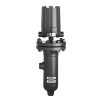
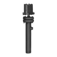
.3.4 Dimensions – Flanged Top Cage Design
inches (mm)
H
L
B
LL
E
C
Plugged
E
7.94*
(
201)
Bottom
connection
F
G
A
HL
LL
E
C
Plugged
E
7.94*
(201)
F
G
A
B
H
L
B
LL
E
C
Plugged
E
7.94*
(201)
1'' NPT
drain
D
F
G
A
HL
LL
1" NPT
drain
E
C
Plugged
E
7.94*
(201)
D
F
G
A
B
Flanged Top Chamber w/NPT or
Socket weld Side/Bottom Connections
(C74, H15, H32, H52)
Flanged Top Chamber w/NPT or
Socket weld Side/Side Connections
(H15, H32, H52)
Flanged Top Chamber
Side/Bottom Flange Connections
(C74, H15, H32, H52)
Flanged Top Chamber
Side/Side Flange Connections
(H15, H32, H52)
Flanged Top Chamber
Side/Side Flange Connections
(C74 only)
HL
LL
Plugged
7
.94
(
201)
C
E
B
E
G
A
F
* These dimensions increase by 2.19 (56) when used
with Series HS switches with terminal blocks.
Housing F G
NEMA 1 4.69 (119) 5.00 (127)
TYPE 4X/7/9*
5.93 (151) 3.78 (96)
TYPE 4X/7/9 Group B*
Conduit Connections E
Electric Switches:
Type 4X/7/9: 1" NPT
Group B: 1" NPT
Pneumatic Switches:
NEMA 1:
1
⁄4" NPT
 Loading...