Sequoia / Tahoe Series User Manual California Instruments
M447352-01 REV-A 99
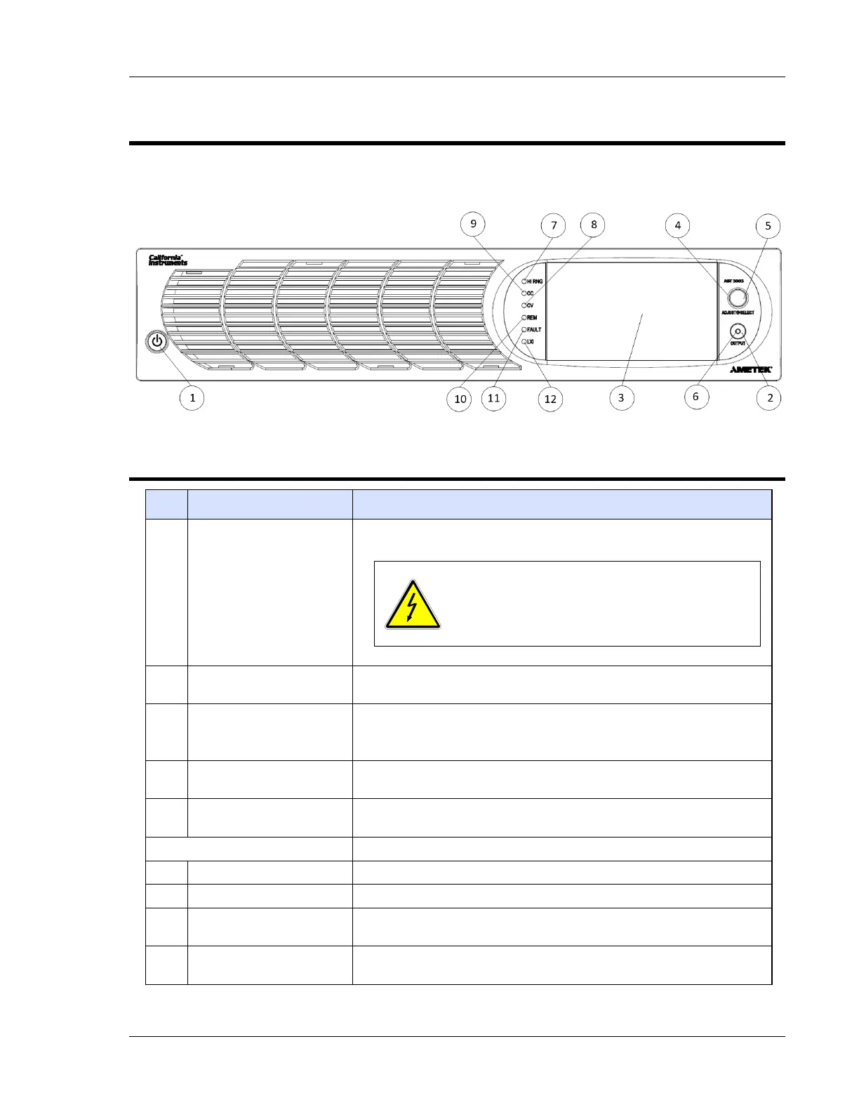
5. Front Panel Operation
Figure 5-1 shows a view of the front panel. Refer to Table 5-1 for functional descriptions of the Enhanced
front panel.
Figure 5-1. Front Panel
5.1 Front Panel Controls and Indicators
Item Reference Functional Description
1 ON/OFF(Standby) Switch
Two–position pushbutton switch turns the source on and off.
WARNING!
The OFF position does not remove AC input from
internal circuits. Disconnect external AC input
before servicing unit
2 OUTPUT Switch
Momentary switch that toggles the output power ON/OFF, and
closes/opens the output isolation relay.
3 Display
TFT color graphics display with backlight and pressure-actuated
touch-screen;
menu-driven settings and functions.
4 Rotary Encoder
Navigates between and within screens; scrolls through functions and
selects numerical values; adjusts output parameters in real-time.
5 Rotary Encoder Switch
Momentary-action switch that selects functions and enters numerical
values.
LED Mode Indicators Indicates the active mode:
6 OUTPUT Output is turned on; the indicator is integral to the OUTPUT switch.
7 HI RNG The output voltage is set to the high-range.
8 CV
All output phases of the power source are presently in Constant-Voltage
mode, and the output voltage is regulated.
9 CC
At least one of the output phases of the power source is presently in
Constant-Current mode, and the output current of that output is regulated.
 Loading...

