EasyManua.ls Logo

Ametek AMP 200N User Manual

Ametek AMP 200N
60 pages
To Next Page IconTo Next Page
Page #1 background imageLoading...
Page #1 background image
M a n u a l
F o r O p e r a t i o n
AMP 200N
AMP 200N1.1
AMP 200N2
Low frequency signal source for supply
simulation and magnetic fields
The AMP 200N series has been designed as a low-frequency
signal source to generate sinusoidal signals used to simulate
ripple noise and ground shift noise as required by a variety of
standards in the automotive, aircraft and military industry.
The AMP 200N devices is controlled by the EM TEST Autowave
to also allow the generation of non-sinusoidal and customized
signals. Additionally, the AMP 200N series can be used to
generate magnetic fields by means of a radiation loop or small
Helmholtz coils.
Ford FMC 1278
Ford EMC-CS-2009
ISO 11452-8
ISO 7637-4 (Draft)
LV 123
SAE J1113-2
Daimler Chrysler DC xx
Fiat 9.90110
GMW3097
PSA/Renault EQ/IR 02
VW TL 82566
Mercedes MBN 10284-2
Nissan 28401 NDS 02
GLoyd GL VI-7-2
4.0.3 / 23.11.2020
The benchmark for emc
4.0.2 / 18.10.2019
UserManual-AMP200N-E-
V4.0.3_reformatted.doc
23.11.20

Table of Contents

Question and Answer IconNeed help?

Do you have a question about the Ametek AMP 200N and is the answer not in the manual?

Ametek AMP 200N Specifications

General IconGeneral
BrandAmetek
ModelAMP 200N
CategoryPortable Generator
LanguageEnglish

Summary

AMP 200N Series Operation Manual

Product Overview and Standards

Introduces the AMP 200N series and lists supported test standards.

Safety Information

Safety Aspects and Warnings

Details general safety precautions, hazards, and warning symbols.

Operator Responsibility and Personnel

Outlines operator duties and required personnel qualifications for safe operation.

Covered Standards

Automotive and Other Standards

Lists automotive and other industry standards the AMP 200N series complies with.

Delivery and Initial Setup

Basic Equipment and Accessories

Lists standard delivery contents and optional accessories.

Optional Features and Modules

Describes available optional software and hardware modules.

Operating Functions

AMP 200N Front View Controls

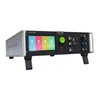
Explains the function of front panel controls and indicators.

AMP 200N Rear View Connections

Details the connectors and ports on the rear panel.

Operating Functions (Specific Models)

AMP 200N1.1/200N2 Front View Controls

Explains front panel controls specific to AMP 200N1.1 and 200N2.

AMP 200N1.1/200N2 Rear View Connections

Details rear panel connections for AMP 200N1.1 and 200N2.

Operation and Test Setup

Test Setup with AutoWave

Guides on setting up tests using AutoWave software.

Output Range Configuration

How to configure output ranges and use as a DC source.

Test Equipment Details

Block Diagram and Construction

Illustrates internal blocks and physical construction of the AMP 200N.

Module Descriptions

Explains the Framebus, Amplifier, and Measuring modules.

Technical Specifications

AMP 200N Specifications

Detailed technical specs for the AMP 200N model.

AMP 200N1.1 Specifications

Detailed technical specs for the AMP 200N1.1 model.

AMP 200N2 Specifications

Detailed technical specs for the AMP 200N2 model.

Maintenance and Calibration

General Maintenance Information

Notes on the maintenance-free nature of the device.

Calibration and Verification Procedures

Guidelines and procedures for calibration and verification.

Applications

General Application Categories

Covers immunity tests and DC source applications.

Capacitive Load Usage

Guidance on connecting capacitive loads.

Test Setup Examples

Illustrates various test setups with other EM Test devices.

Ford EMC CS 2009-1 Setup

Specific setup for Ford EMC CS 2009-1 standard testing.

Magnetic Field Immunity: RI 140

Setup for magnetic field immunity testing as per RI 140.

Coupled Immunity: RI 150 Setup

Setup for coupled immunity testing as per RI 150.

CI 210: Continuous Power Line Disturbances

Setup for immunity to continuous power line disturbances (CI 210).

CI 250: Ground Voltage Offset Immunity

Setup for immunity to ground voltage offset (CI 250).

CI 250 Transient Disturbances

Setup for CI 250 transient disturbance testing.

SAE J1113-2 Immunity Test

Setup and parameters for SAE J1113-2 immunity testing.

GLoyd GL VI-7-2 (DC) Immunity Test

Setup for GLoyd GL VI-7-2 DC immunity testing.

Ripple Immunity: Voltage and Current Measurement

Setup for ripple immunity testing using voltage and current measurement.

Software Setup: Voltage and Current Monitoring

Guides on software configuration for monitoring voltage and current.

Waveform Verification

RI 140 H-Field Verification

Procedure for verifying RI 140 H-field measurements.

CI 250 Pulse Verification

Procedure for verifying CI 250 pulse characteristics.

Appendix

Declaration of CE-Conformity

Official declaration of conformity with CE directives.

Radiating Loop H-Field vs. Antenna Current

Graph illustrating the relationship between H-field and antenna current.

Related product manuals