Do you have a question about the Ametek 200 Series and is the answer not in the manual?
General safety considerations and compliance with Installation Category II.
Defines the operator's duties regarding safe use and potential interference.
Highlights hazards associated with high voltages and equipment operation.
Describes the safety circuit function to switch off high voltage and the TEST ON button.
Emphasizes the need for trained operators and understanding of standards.
Details on power supply, grounding, and connections for safe testing.
Warnings about potential EUT defects, ignition, or unexpected movement.
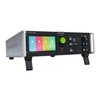
Details the front panel controls and display of 19" units.
Describes the rear panel connectors and interfaces for 19" units.
The AMETEK 200-series Automotive Transient Immunity Test Generators are designed for EMI immunity testing of electronic equipment and devices in industrial environments, particularly for automotive applications. These generators are capable of producing defined interference signals such as ESD, EFT, and conducted RF, ensuring compliance with international, national, and manufacturer's test standards.
The 200-series generators, including models like UCS 200Nx, LD 200Nx, VDS 200Qx, PFS 200Nx, MPG 200S21, RCB 200Nx, and SNG 200Px, are built into 19" housings and feature a common front panel control with a large display for ease of operation. They generate various transient test pulses that are superimposed onto the battery supply voltage inside the generator. The primary function is to simulate electrical disturbances that an automotive electronic device might encounter, ensuring its robust operation.
The UCS 200N, for example, is an Ultra Compact Simulator for automotive applications, capable of generating Micro Pulses, Burst Pulses (3a/3b), and Freestyle pulses. The LD 200N is designed for load dump pulses, while the PFS 200N handles power fail simulations. The VDS 200Qx and VDS 200R-series are equipped with additional "FrameBus" connectors for system integration. The RCB 200Nx is specifically designed for relay switching tests, and the SNG 200Px is used for generating specific sequences of transients.
The generators incorporate a safety circuit that, when activated, disconnects the internal power supply of the high voltage control, ensuring operator safety. A warning lamp function is also available to indicate active testing, which can be used to control external warning lamps or other safety devices in the test setup.
Power Supply: The equipment operates with a power supply not exceeding 250 volts between phase and neutral or phase and ground. A proper ground connection via the power cord is essential. Voltage selectors (115V/230V) are present on some units, and fuses must be replaced according to the selected mains voltage. The generators themselves do not have built-in fuses for the EUT power supply; external protection for the EUT is the user's responsibility, with fuse dimensions matching or smaller than the rated EUT current.
Safety Circuit: Powered by 24VDC, the safety circuit disconnects the high voltage control's internal power supply. For external wiring, a twisted pair screened cable (current max. 2A) is recommended. Note that the EUT power supply is not disconnected by the safety circuit; a special electrical circuit must be designed by the user for this purpose.
Warning Lamp: The voltage-free contact for the warning lamp supports 230V AC/DC, 6A. It is designed with two 2.2nF 250V Y-type capacitors for interference filtering. Generators supporting this feature include LD 200 M, LD 200N, UCS 200M, and UCS 200N.
Interfaces: Most 200-series units feature various interfaces for remote control and system integration:
RCB 200Nx Specifics:
SNG 200Px Specifics:
Front Panel Control: The 200-series generators are designed for intuitive manual operation via the front panel.
Software Operation: Most generators can be operated remotely via software (e.g., iso.control or autowave.control). This allows for complex test sequences, configuration, and report generation. The software provides a graphical interface for setting up tests, browsing standards, and monitoring test progress. The "TEST ON" button on the generator must be activated to start a test via software.
Test Setup Examples: The manual provides common setup diagrams for various test scenarios, including transients and dropouts, illustrating how different 200-series units (RDS, LD, AutoWave, PFS, UCS, VDS, AMP) are interconnected with the DUT and other accessories. Proper grounding to a reference ground plane is emphasized for all components.
Coupling Networks: Generators and coupling devices must be grounded and connected to the reference ground. Special safety adapter cables are part of the delivery. Coupling clamps, as defined by standards, must be connected and adjusted according to losses, and users are warned not to touch them during test runs due to high voltage hazards.
General Maintenance: The generators do not contain user-serviceable parts. All electrical maintenance, adjustments, and replacement of parts must be performed by experienced and specially trained technicians. The user is explicitly prohibited from changing or modifying any EM TEST / TESEQ generator. Only original EM TEST / TESEQ parts and components should be used for repair and service.
Safety during Maintenance: High voltage parts may be exposed when covers are removed. The generator must be disconnected from all power supply sources before any covers are removed for service, repair, or adjustment.
Calibration and Verification: AMETEK CTS recommends annual calibration. Verification should be performed regularly according to the applicable standard. Calibration adapters are recommended for voltage impulse calibration and verification, and strict adherence to safety warnings is required during these procedures, especially regarding mains supply on the output.
Disposal: Electronic devices must be disposed of according to country-specific regulations, ideally at a specialized waste collection center. EM TEST and Teseq devices can be returned to AMETEK CTS in Switzerland or their agencies for proper disposal. Capacitors do not contain polychlorinated biphenyl (PCB), but back-up and rechargeable batteries must be disposed of separately.
| Brand | Ametek |
|---|---|
| Model | 200 Series |
| Category | Portable Generator |
| Language | English |