AMETEK CTS Automotive Transient Immunity Testing
1.00 7 / 26
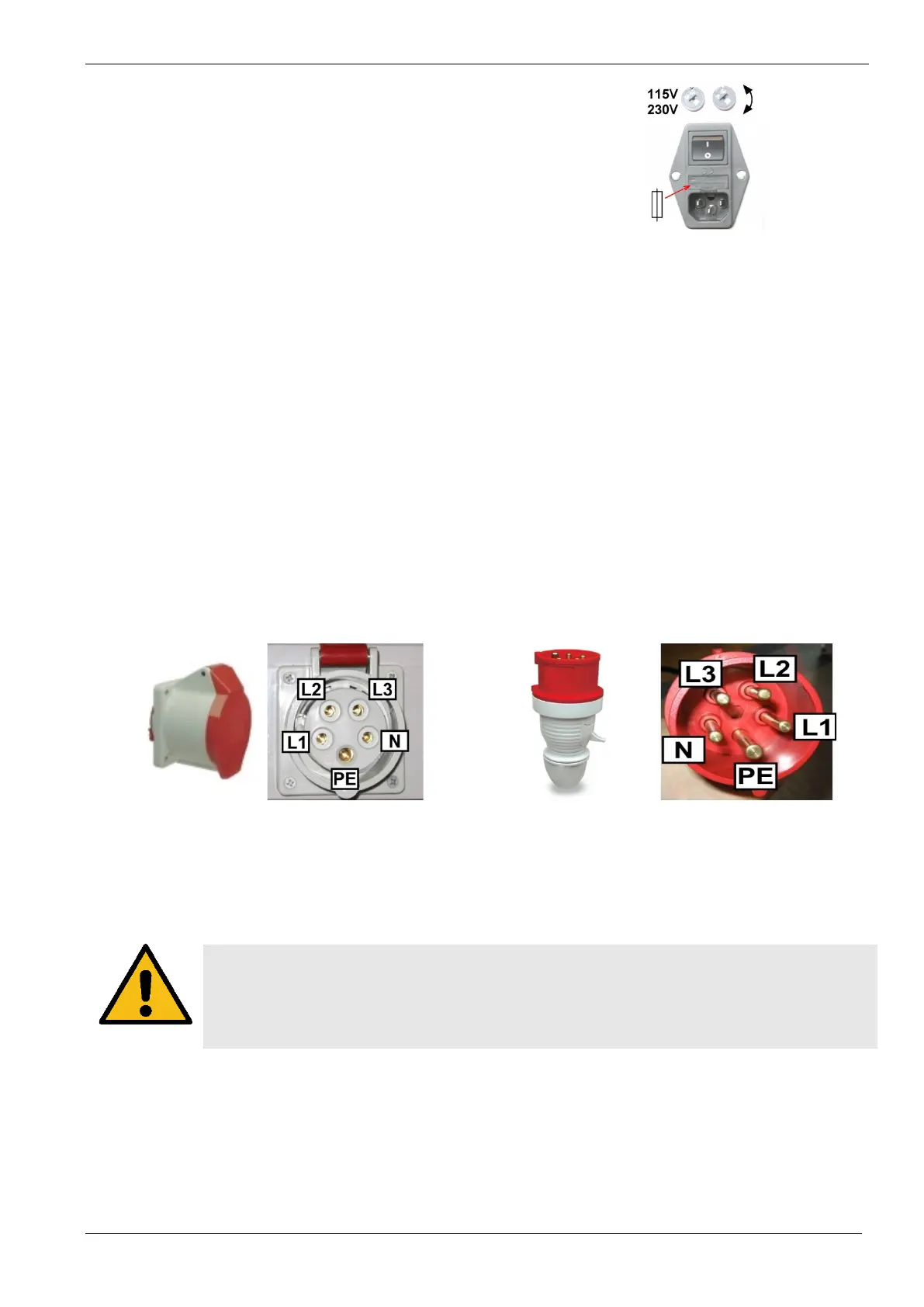
First check the 115 V / 230 V voltage selector where applicable!
Do not connect 230 VAC into the 115 VAC units.
The result could be a severely damaged unit.
Figure 5 - Voltage Selection
If power to the equipment of Class I is supplied by an auto-transformer which is connected to a higher supply
voltage, the base of the auto-transformer must be connected to the neutral of the power supply.
Equipment of Class I, which is supplied with a 3-phase power cord, must only be connected to a grounded
receptacle. The protective ground connection must not be disconnected or otherwise interrupted.
Each interruption or disconnection of the protective ground connection inside or outside the equipment may cause
electric shock.
Connecting different units with each other or to a personal computer for remote control may be performed only with
cables recommended and/or supplied by the manufacturer.
1.8. 3-phase EUT power lines
The connectors for 3-phase EUT power lines on the devices is realized with CEE connectors.
Take care to connect carefully the correct plugs during installation.
Important is a direct connection between neutral and PE from the power supply. Otherwise you get problems with
the floating neutral star point and inconvenience or malfunctions during the test.
The figures show the correct mapping of the plugs of the CEE connectors.
Figure 6 - Female Connector
Figure 7 - Male Connector
1.9. Fuse for the EUT power supply
The pulse generators have no built in fuse for the EUT power supply. It is in the scope of responsibility of the user
to protect the EUT external for the rated current.
CAUTION
CAUTION: The design of the external fuse must be matching the following rules:
- fuse dimension must be equal or smaller than the rated EUT current of the connected test
generator
- fuse must be designed for protect the connected EUT device under test in malfunction
 Loading...