AMETEK CTS Automotive Transient Immunity Testing
1.00 12 / 26
4. Operating Elements 200-series
Many of the 200-series generators, such as UCS, LD, PFS, VDS, MPG, are built into a 19” housing, use a
common front panel control and have a large display. Operating element as well connectors are similar, but not
all connectors, in- and outputs and interfaces are available at all generators.
Discription below refers to the UCS 200Nx generator.
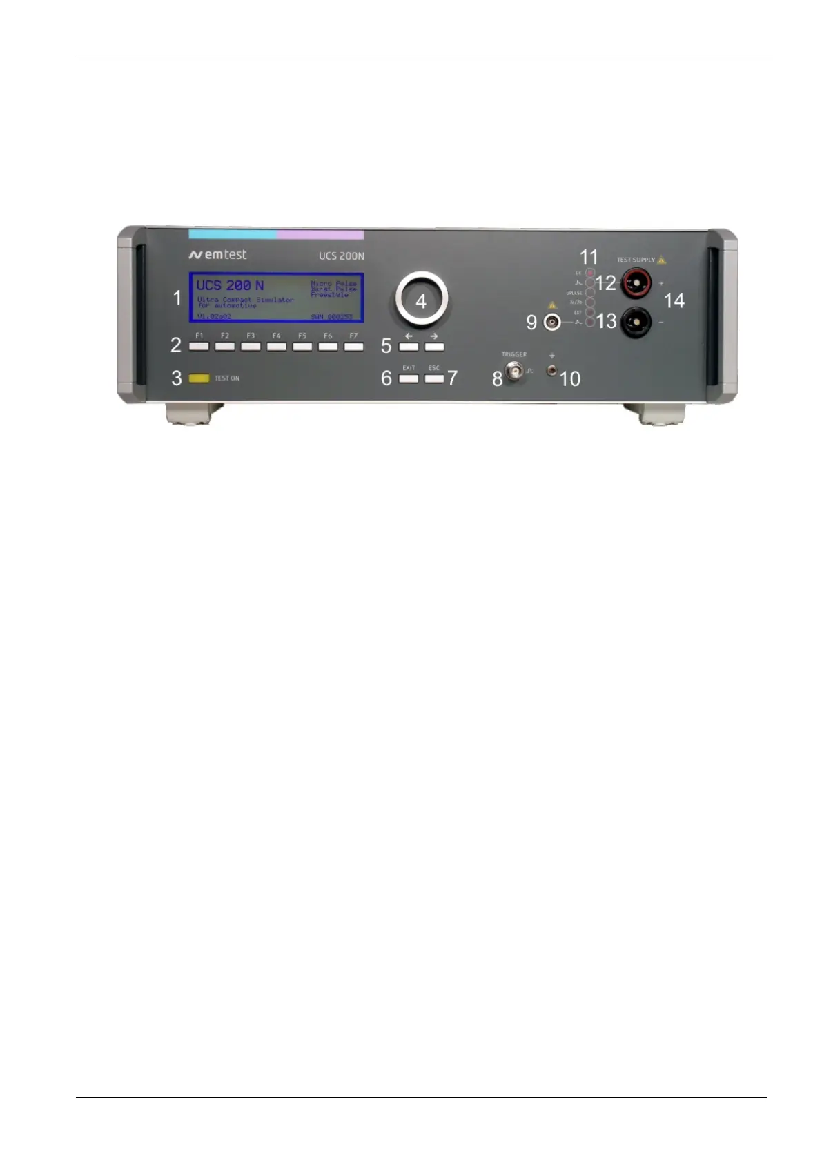
4.1. Front view 19” units
Earth connector for verification
1 Display
All functions and parameters are displayed (8 lines with max. 40 characters).
2 Function keys "F1 .. F7"
Parameters and functions, displayed in the lowest line, can be selected with the related function key.
3 TEST ON
By pressing the key "TEST ON" the TEST SUPPLY output is activated and a test can be startet. indicates
4 Knob (Inc / Dec)
The knob increments or decrements test parameters with a numeric value or selects from a list of
parameters.
5 Cursor keys
Parameters and functions can be changed on-line. The selection of these parameters is realized with the
cursor moving to the left or to the right.
6 EXIT
Pressing of the Exit function will cause a reset of the firmware. This is only possible if no test routine is
running.
7 ESC
When pressing the ESC button the user gets back one page in the menu.
8 TRIGGER (selected generators only)
At the BNC CRO Trigger output, the generator trigger can be checked, e.g. the burst duration, the burst
repetition rate and the spike frequency (+15 V rectangular). This output signal can also be used to trigger
external measuring devices (e.g. an oscilloscope).
9 HV pulse output 50 ohm (selected generators only)
External coupling devices such as the capacitive coupling clamp are connected to the coaxial 50 ohm output.
Also the pulse parameters, on open circuit and 50Ω load condition (pulses 3a/3b), must be verified at this
coaxial output.

 Loading...