AMETEK CTS Automotive Transient Immunity Testing
1.00 8 / 26
2. Safety functions
The test area must be organized so that only those involved in the test may enter it. In the case that the safety
circuit is used to control the complete area, an additional interlock contact must be used to directly protect the
operator from contact with the DUT.
Neither the DUT nor any cables or accessories must be touched during the test. During work on the DUT, the test
procedure must be stopped and the DUT disconnected from the power mains supply.
Coupling devices have no safety functions built in, because these functions are integrated in the generators.
2.1. Safety circuit
The safety circuit will switch off the high voltage and the TEST ON button of the unit.
2.1.1. Safety circuit for 200, series
The safety circuit is powered by 24VDC and disconnects the internal power
supply of the high voltage control. For external wiring use twisted pair screened
cable (current max. 2A).
The EUT power supply will not be disconnected when the safety circuit is open.
To disconnect the EUT power, the user must design a special electrical circuit.
Figure 8 - Safety Circuit
Devices with no safety circuit:
ISO Generators: PFM 200, PFS 200, RCB 200, RDS 200, VDS 200, AutoWave, AMP200 (12V)
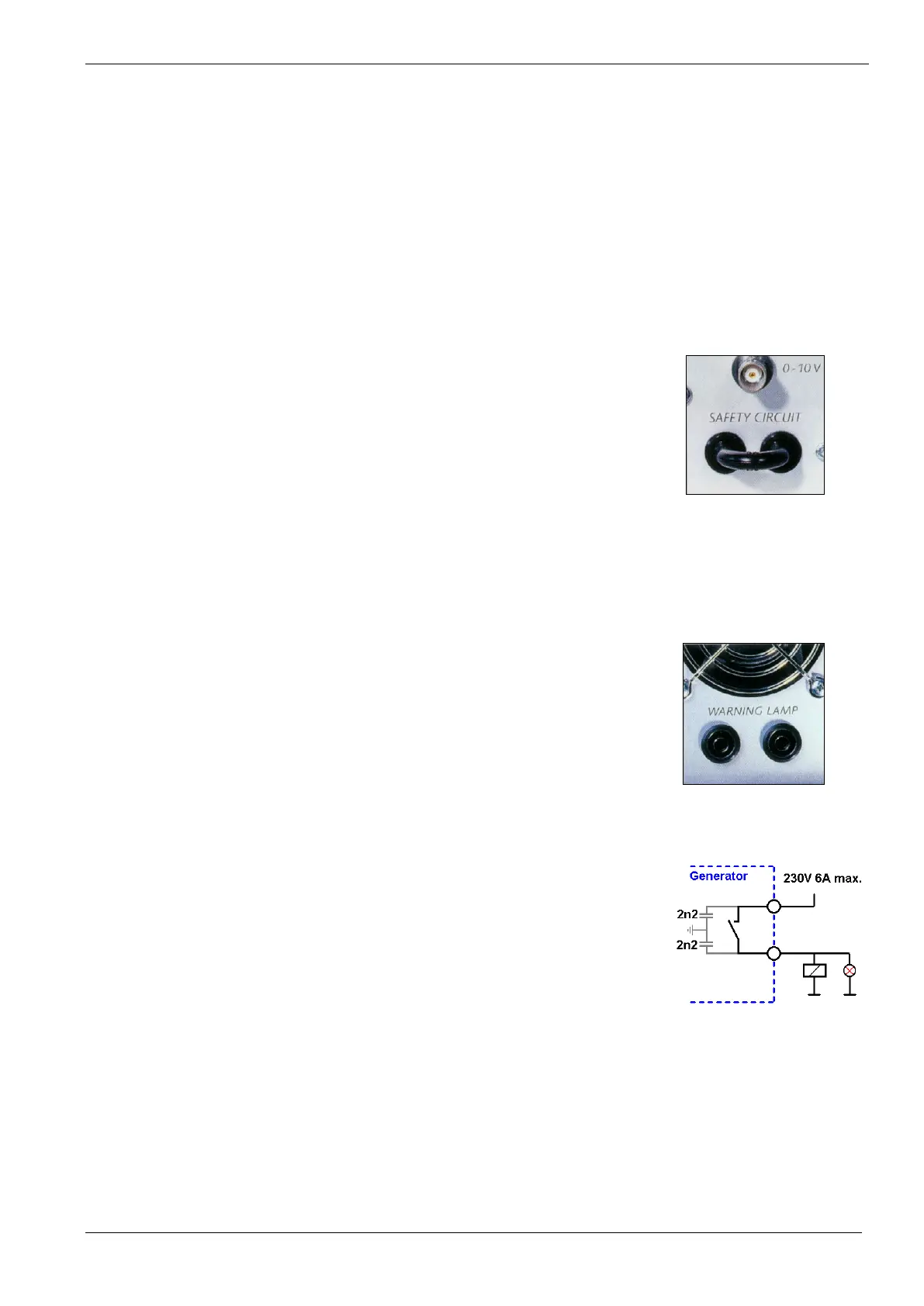
2.1.2. Warning lamp 200-series
The EUT must be tested within a safety box or within a protected area. In
extreme circumstances the DUT may explode or ignite.
The available “Safety Circuit” and “Warning Lamp” functions can be used to
provide additional protection for the operator.
Function
Active: Test ON button is released and the safety circuit is closed.
Inactive: Test ON is OFF or the safety circuit is open
This voltage free contact provided can be used for switching external warning
lamps or other safety devices. For filtering interference’s, two 2.2nF 250V Y-type
capacitors are connected in the circuit.
Max. Power: 230V AC/DC, 6A
Generators: LD 200 M, LD 200N, UCS 200M, UCS 200N
Figure 10 - Wiring Diagram
2.1.3. Earthing of devices
Earth Bolt, When equipped
Generators must be grounded to the reference ground plane. Generally, the generators are equipped with a
metal earth bolt (8 mm x 30 mm, or 18,5 mm x 22 mm) at the rear side of the device.
 Loading...