AMETEK CTS Automotive Transient Immunity Testing
1.00 17 / 26
4.3. RCB 200Nx
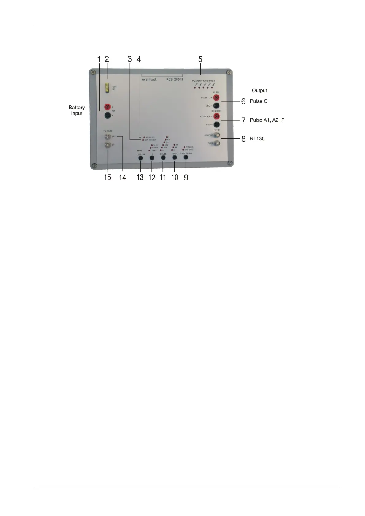
Figure 2.1
BAT input 13.5V ( Power supply RCB 200N1)
START / STOP ; LED endless / sequence
PULSE Transient pulse selection
Indication Relays EOL (end of lifetime)
Transient Generator switching
Pulse C Output CI 220, CI 260
Pulse A, F Output CI 220, CI 260
Pulse Output RI 130 (BNC)
1 Battery input
Power supply input for RCB200N1, nominal 13.5Vdc (max 18Vdc)
2 Fuse
Fuse 20A for device protection
3 Ext. Trigger mode
Indication of external Trigger mode. The controller detect when the bridge between Trigger OUT – Trigger In is
disconnected. In this Mode the user has to connect an external trigger signal for relays switching.
4 Relays EOL End of Lifetime indication
The lifetime of the Potter & Brumfield relays is limited by the erosion during BURST testing. The operating
duration is limited to 100hours.
- LED blinking: Lifetime is within 10 hour of max liftime
- LED on: The test will be stopped. The user must replace the relays.
5 Transient generator switch settings
The selected pulse the Ford standard recommends to set different switches. The LED indicates the internal
relays setting according the Ford Standard
6 Pulse C output to DUT
Output plugs for testing pulses C-1 and C-2 as per CI 220
7 Pulse A, F output to DUT
Output plugs for testing pulses A1, A2-1, A2-2 and F as per CI 220 and CI 260
8 Pulse output to clamp
Output BNC plugs for testing as per RI 130. The BNC plugs are internal shorted when RI130 is not selected.

 Loading...