AMETEK CTS Automotive Transient Immunity Testing
1.00 19 / 26
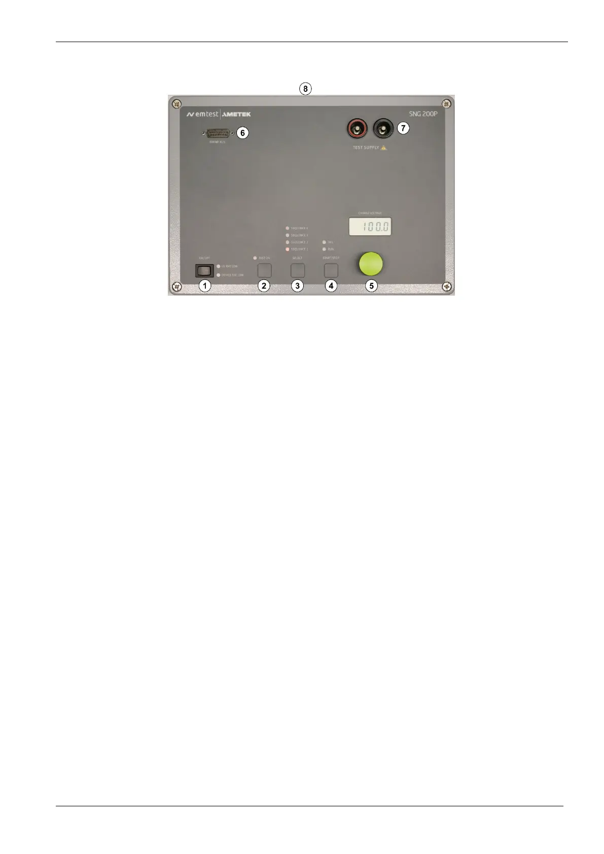
4.4. SNG 200Px Operating Elements
1 Power ON/OFF and Battery Indicator
The ON/OFF button sets turns the generator on and off. LEDs are provided to show when the battery gets low.
2 Test Enable Button “TEST ON”
Pressing the "TEST ON" button enables testing. The LED serves also as an optical indication when the switch
switches: the DUT power will be provided when the button is lit.
3 Sequence Select and Indicator
Pressing the SELECT button to choose the pre-programmed SEQUENCE 1…4. These sequences are sent
from autowave.control
4 START/STOP Button
Press to start or stop the test. The RUN indicator will light when the test is running.
The FAIL light will light in case of an error.
5 Charge Voltage Set and Indicator
Turn this know to set the voltage up to 100.0V. The TEST ON must be disabled to change the voltage.
6 Framebus Connction
Connects to an AutoWave to send the sequences to the SNG 200N. Device an internal terminator.
7 DUT Test Supply
DUT output HIGH (red) and LOW (black) with 4 mm (male) / 6 mm (female) connectors
8 Earthing Connector (Side, not shown)
A banana jack is provided for safety

 Loading...