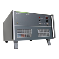
AMETEK CTS AMP 200N series
Manual for Operation V 4.0.3 3 / 60
Contents
1 Safety................................................................................................................................ 5
1.1 Safety Aspects .................................................................................................................................... 5
1.2 Safety and warning label on the device .............................................................................................. 5
1.3 Responsibility of the operator ............................................................................................................. 6
1.4 General hazard ................................................................................................................................... 6
1.5 Qualification of personnel ................................................................................................................... 7
2 Standards covered by AMP 200N Series ....................................................................... 8
2.1 General ............................................................................................................................................... 8
3 Delivery Groups and Put in service ............................................................................... 9
3.1 Basic equipment AMP 200N Series ................................................................................................... 9
3.2 Accessories ...................................................................................................................................... 10
3.2.1 Frame Bus Termination .................................................................................................................... 10
3.3 Options ............................................................................................................................................. 10
4 Operating Functions AMP200N .................................................................................... 11
4.1 Front view ......................................................................................................................................... 11
4.2 Rear view .......................................................................................................................................... 12
5 Operating Functions AMP200N1.1 and AMP 200N2 ................................................... 14
5.1 Front view ......................................................................................................................................... 14
5.2 Rear view .......................................................................................................................................... 15
6 Operation ....................................................................................................................... 19
6.1 Test Setup with Autowave ................................................................................................................ 19
6.1.1 Cabeling with Autowave ................................................................................................................... 19
6.2 Test Setup and cabeling with Netwave and AMP200N Series ........................................................ 19
6.3 Output Range setting for DC application .......................................................................................... 20
6.3.1 AMP 200Nx as DC source ................................................................................................................ 20
7 Test Equipment AMP 200N ........................................................................................... 22
7.1 Blockdiagram .................................................................................................................................... 22
7.2 Construction...................................................................................................................................... 22
7.3 Cooling .............................................................................................................................................. 22
7.4 Framebus Interface Module .............................................................................................................. 23
7.5 Amplifier ............................................................................................................................................ 23
7.6 Measuring Board .............................................................................................................................. 23
8 Technical data AMP200N .............................................................................................. 24
8.1 Amplifier output characteristics......................................................................................................... 24
8.2 Signal generator output characteristics (built in) .............................................................................. 24
8.3 Measurements (optional) .................................................................................................................. 24
8.4 General ............................................................................................................................................. 24
9 Technical data AMP200N1.1 ......................................................................................... 25
9.1 Amplifier output characteristics......................................................................................................... 25
9.2 Signal generator output characteristics (built in) .............................................................................. 25
9.3 Measurements (optional) .................................................................................................................. 25
9.4 General ............................................................................................................................................. 25
10 Technical data AMP200N2 ............................................................................................ 26
10.1 Amplifier output characteristics......................................................................................................... 26
10.2 Signal generator output characteristics (built in) .............................................................................. 26
10.3 Measurements (optional) .................................................................................................................. 26
10.4 General ............................................................................................................................................. 26
11 Maintenance ................................................................................................................... 28
11.1 General ............................................................................................................................................. 28
11.2 Calibration and Verification ............................................................................................................... 28
11.2.1 Factory calibration ............................................................................................................................ 28
11.2.2 Guideline to determine the calibration period of AMETEK CTS instrumentation ............................. 28
11.2.3 Calibration of Accessories made by passive components only ....................................................... 28
11.2.4 Periodically In-house verification ...................................................................................................... 28
12 Application ..................................................................................................................... 29

 Loading...