Doc No. 740124 15
MODEL 9 SERIES WELD HEAD
OPERATION MANUAL
8.0 SHIELDING GAS (cont’d.)
Note: If the system is being hooked up for the first time, or if it has been a
number of hours since it was last used, it’s a good idea to initiate the
Manual Purge button on the power supply to clear the lines of
oxygen for a few minutes before initiating a weld sequence.
9.0 RETURN-TO-HOME (ROTOR) POSITION ADJUSTMENT
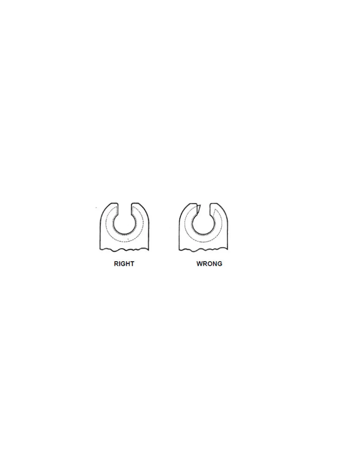
The Model 9 series weld heads will return the rotor to the “home” (open) position
at the end of the weld program, after the post purge time has timed-out. A
properly adjusted rotor will stop with both ends of the rotor flush or slightly
recessed in the housing. A rotor that needs adjustment will either stop with one
side of the rotor protruding out from the housing, or in a worst case, the rotor
does not stop at all after it returns to home, in which case, the power supply
would have to be shut down before attempting any adjustment. See fig. 17.
Fig. 17
Should your Model 9 require return-to-home adjustment, follow these steps:
9.1 Be sure the power supply is either turned off or in the “TEST” mode.
9.2 Remove the screws holding the lower of the two access covers over
the return-to-home limit switch.
9.3 For Models 9-750 series and 9-1500 series heads, loosen the screw
on the left that holds the return-to-home limit switch bracket. See fig.
18.