Doc No. 740124 8
MODEL 9 SERIES WELD HEAD
OPERATION MANUAL
6.0 CLAMP INSERT & GAS SEAL INSTALLATION (cont’d.)
Fig. 6
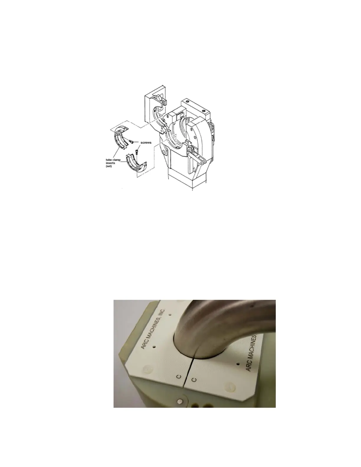
6.2 Model 9E and 9ER type heads use a clamp insert on one side, and a
gas seal on the other side of the head. The hole in the gas seal is
approximately 1/8” (3mm) larger than the diameter of the part to be
welded. Components such as elbows or other non-straight or odd-
shaped parts will sometimes require repositioning of the gas seal to
facilitate approximately a 1/16” (1.6mm) gap all around the part being
welded. This gap is used to allow arc gas to exit the weld head and to
minimize gas seal burning. The four mounting holes in the gas seal
are large enough to allow the gas seal to be positioned as required.
Blank gas seals (without a hole in the center) are available for
custom applications. See fig. 7.
Fig. 7
Model 9ER-4500



 To Next Page