ELECTRICAL
C. ELECTRICAL
NOTE: POWER SHOULD BE BROUGHTTOTHE UNITONLY AFTER ALLTHE MODULES
ARE CONNECTED TO THE MOTHERBOARD.
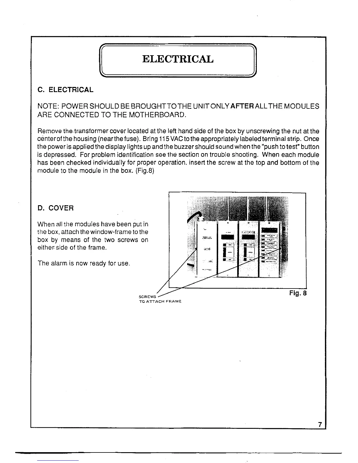
Remove the, transformer cover located at the left hand side of the box by unscrewing the nut at the
center of the housing (nearthe fuse). Bring 115 VAC to the appropriately labeled terminal strip. Once
the power is applied the display lights up and the buzzer should sound when the "push to test" button
is depressed. For problem identification see the section on trouble shooting. When each module
has been checked individually for proper operation. insert the screw at the top and bottom of the
module to the module in the box. (Fig.8)
D. COVER
When all the modules have been put in
the box, attach the window-frame to the
box by means of the two screws on
either: side of the frame.
The alarm is now ready for use.
SCREWS
TO ATTACH FRAME
Fig. 8
7
 Loading...