Ampac
7 Ledgar Road, Balcatta, Western Australia 6021
Telephone: +618 9201 6100 Fax: +618 9201 6101
Email: Info@Ampac.net Website: www.Ampac.net
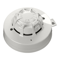
XP95 Open-Area Sounder and Sounder Visual
Indicator Installation Guide
General
This guide refers to the Outdoor (Type B) XP95 Open-Area Sounder, but the installation process
is identical for all products listed below:
Item Number Product Description
4107-4002 XP95 Open-Area Sounder Red Body (AS7240-3)
4107-4003 XP95 Open-Area Sounder White Body (AS7240-3)
4107-6003 XP95 Open-Area Sounder Visual Indicator (AS7240-3)
The sounder is connected to control panels which use the Discovery or XP95 protocol. It com-
plies with the requirements of AS7240-3.
The sounder is supplied with an isolating base. A yellow LED is illuminated if a loop short circuit is
detected.
The tones incorporated in the sounder products are:
Australian AS7240-3 Tone, New Zealand NZS4512 Tone & Apollo Standard Tone.
There are two volume settings in each sounder variant.
Installation
1. Drill out the cable entries and mounting holes as required on the base (using a 20mm hole
cutter for the cable entries), taking care not to damage the electronics. Do not attempt to
knock these out as the base will be damaged.
2. Secure the base to the mounting surface with pan-head screws. If IP65 integrity is required,
fi t the weatherproof mounting pad between the base and the mounting surface. Fit the
‘O’ ring to the base (Fig. 2) using a lubricant such as silicone grease.
3. Set the sounder address using the table overleaf.
4. To lock the sounder in the base, snip the break-out on the base rim (location shown in Fig. 2).
Fit the sounder to the base.
39215-213/Issue 1
Functional Test Data
The sounder is loop-powered and controlled by the control panel using the output bits in the
communication protocol.
Troubleshooting
Before investigating individual units for faults, it is important to check the system wiring is fault-
free. Earth faults on data loops may cause communication errors.
Fault Finding
Problem Possible Cause
No response or missing Incorrect address setting
Incorrect loop wiring (polarity reversed)
Analogue value 1 Sounder failed
Analogue value 4 Incorrect group or individual address setting
Device fault Incorrect group address setting
Device fails to operate Control panel has incorrect cause and effect
programming
Incorrect group address setting
Incorrect tone setting
Device diffi cult to fi t to base Insuffi cient lubricant on ‘O’ ring
Water ingress Weatherproof mounting pad missing or
damaged
Incorrect cable glands
Damaged base
L+ In
L– In
E
L+ Out
L– Out
E=Earth/Screen
Mounting Holes
Fixing centres 51mm and 60mm, 5mm diameter (max) clearance
Locking Mechanism
Isolator LED
© Apollo Fire Detectors Limited 2007-10 TP/TB
Weatherproof mounting pad
‘O’ ring
‘O’ ring
Fig. 2- Base diagram
1
4