www.SteamPoweredRadio.Com
INTERCONNECTING
Re
ga
rdless
of
application observe
the
re
quir
ements
und
er "Line
Input"
and "Reproduce
Output"
when
interconnec
ting
the
machine with
an
y
other piece
of
equipment.
3-2
CONNECTORS
A power cable and marching plugs for the
MICROPHONE
(JI
01S
),
LINE
INPUT
(]10
2S),
and
OUTPUT
(JI
04S)
connectors
are
s
up
-
plied
with
the
equipment.
Shielded, low-capacity cable is re
comme
nded for
making
up
input
and
output
cables. Make such cables as shore as possible for intercon-
ne
c
ting
units in
audio
systems.
Refer
co
the
schematic diagram ( Fig.
5.3),
to
determin
e correct
pin
conn
ec
ti
on for all plugs.
STUDIO
The
reproduce head
cab
le is d
ou
ble shielded, insuring against r-f
INSTALLATION
pi
ckup. Cable capacity and length have been minimized
co
avo
id
high
frequency loss. In general, mo
unt
the
electro
ni
c assembly and cape trans-
port
no mo
re
than
o
ne
foot apart.
If
che r
epro
du
ce head cable is len
gt
h-
ened for gr
ea
ter separation of
the
components, high fre
qu
ency response
wi
ll
be
affected. In the
eve
nt an in
sta
llation absolutely d
ema
nds len
gth-
ening
thi
s cable, a very low capacity rype (
RG
-62/
U)
is
in
dicated, plus
the
addition
of
an
ourer shield.
Hi
gh fr
eq
uen
cy
losses cannot be ke
pt
co
a
minimum
if
the
cable l
ength
exceeds three feet.
Space requirements for custom installation
are
given in the accom-
panyin
g illu
st
rati
on ( Fig.
3-
1
).
All
ow
suffi
cient
clearance
at
the
right
side
of
the electronics chassis for easy access
to
LINE
INPUT
and
OUT
-
PUT
co
nn
ecto
rs.
If
desired, these conneccors can
be
brought
co
a parch
pane
l
mounted
at
some
more convenie
nt
point in
the
inscallacion ro
pr
o-
vide ready accessibility.
Fig.
3-
1. Space R
eq1
ti
rcments
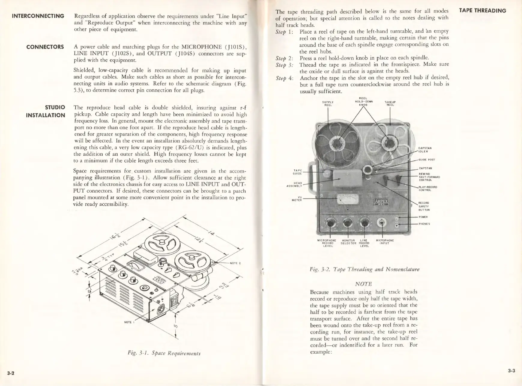
Th
e cape threading
path
described bel
ow
is
the
same for all modes
of operation; but special attention is ca
ll
ed
to
the
notes dealing
with
half crack heads.
St
ep
1: Place a r
ee
l of cape on
the
left-hand
cu
rnrable, and iui
empty
ree
l
on
the
ri
gh
t-hand
turnt
able,
making
certain
tha
t
the
pins
around rhe base of each
sp
indle en
gage
cor
responding s
loe
s
on
the
reel
hub
s.
Step 2:
St
ep
3:
Press a reel hold-down
knob
in place on each spi
ndle
.
Thr
ead
the
cape as indicated in
th
e fro
nti
spiece.
Mak
e sure
the
ox
i
de
or dull surface is against
th
e heads.
Step
4:
Anchor
the
rape in rhe slot
on
the
em
pry r
ee
l
hub
if desired,
but
a
full
cape
turn
councerclockwise around che reel
hub
is
usua
ll
y sufficient.
HEAD
ASSEMBLY
REEL
MI
CROPHO
NE
MONITOR
LINE
MI
CROPHO
NE
RECORD
SELECTOR
RECORD
INPUT
LEVEL
LEYEL
CAPSTAN
IDLER
GUIDE
POST
CAPSTA
N
R
EWIND
FAST·FORWARD
CONTROL
Pl.AY-RECOAO
CO
N
TROL
RECORD
SAFETY
BUTTON
Fig.
3-2
.
Tap
e Threading
and
N omenclatNre
NOTE
Because machines using half track heads
record
or
reproduce only half
the
cape wi
dth,
the
t
ape
supp
ly
must
be
so
oriented chat
th
e
half
to
be
recorded is farthest from
th
e cape
transp
ort
surface.
After
the
e
ntir
e rape has
been wound onto che take
-up
reel from a re-
cording
run, for instance,
the
take-
up
r
ee
l
muse
be
turned over a
nd
the
second half re-
corded--or
indencifi
ed
for a lacer
run.
For
ex
ample:
TAPE THREADING
3-3