www.SteamPoweredRadio.Com
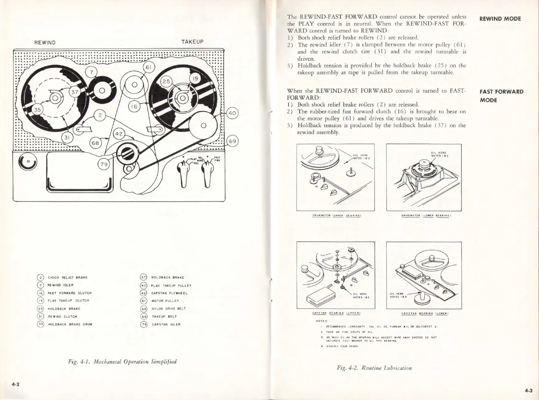
REWIND
TAKE
UP
0
SHOCK RELIEF BRAKE
@)
HOLDBACK
BRAKE
0
REWIND IDLER
e
PLAY
TAl<EUP
PULLEY
@
FAST
FORWARD CLUTCH
@
C
APSTAN
FLY
WHE
EL
e
PLAY
TAKEUP
CLUTCH
e
MOTOR
PULLEY
@)
HOLOBACK BRAKE
@)
NYLON
DRIVE
BE
LT
(0
REWIND
CLU
TCH
@
TAKEUP
BELT
@
HOLDBACK BRAKE
ORUM
@
CAPSTA
N
IDLER
Fig.
4-1.
Mechanical Operation Simplified
4-2
The
REWIND-FAST
FORWARD
control cannot
be
operated unless
rhe PLAY control
is
in
neutral.
When
th
e
REW
I
ND-FAST
FOR-
WARD
control
is
turned
co
REWIND:
I )
Both
shock relief brake rollers (
2)
are released.
2)
The
rewind idler (
7)
is
clamped between
the
mocor pulley (
61
/
and
the
rew
ind clutch
tire
( 3 l )
and
the
rewind
turntable
is
driven.
3)
Holdback tension is provided by
the
holdback brake (
25)
on
the
rakeup assembly as tape
is
pulled from
the
cakeup turntable.
When
the
REWIND-FAST
FORWARD
control
is
turned
co
FAST-
FORWARD:
1)
B
oth
shock relief brake rollers (
2)
are
released.
2)
The
rubber-tired fast forward clutch (
16)
is
brought
co
bear
on
the
moror pulley (
61)
and
drives the cakeup
turntab
l
e.
3)
Holdback tension is produced by
the
holdback brake
(37)
on
the
r
ewind
assembly.
N
OTE
5
OIL
HC
A[
N0TCS
l 6
'l
4 fllCCO
MM
CNOEO
LU8
R
1C
ANT
5
CAL
OIL
OC,
TUR
9lN
[ •
11.
OR
8Ulf'C:A£5T
.t,
i! FOUR QA
FIVE
0FIOP5
or
OtL
l
"-$
M
UGi.
OIL
AS
T~C
8EAAING
W
ILL
A
CCEPT
WIPf.
A
WA
Y
f:ICCESS
00
N
OT
SATUAAlE
Fhl
WASI-CCR
TO
OIL
THIS
ftE•AING
~
CXACll'f
rouR
0R0PS
Fig. 4-2. R
outine
L1tbrica1ion
REWI
ND
MODE
FAST
FORWARD
MODE
4-3