3
• Select a channel (1-16) on side panel (I) of bodypack using the
supplied screw driver to select channel number. Channel select-
ed should match channel on receiver. When transmitter and
receiver are set to correct channel the RF INDICATOR (B) will glow
red when transmitter is turned on.
• Plug the Lapel / Headset microphone into the MIC INPUT JACK (K).
The lapel microphone can be clipped to a necktie or other cloth-
ing, using the supplied clip. The lapel mic should be placed under
the chin, as close to the center of the body as possible.
• Slide the power ON / OFF switch (J) to the ON position, the LED
INDICATOR LIGHT (L) will illuminate green. Replace batteries when
this LED turns red.
● MUTE LEVEL ON RECEIVER (F) is set at half way mark when it
leaves the factory. If speaker sound is breaking up, turn level
clockwise with small screwdriver until condition improves.
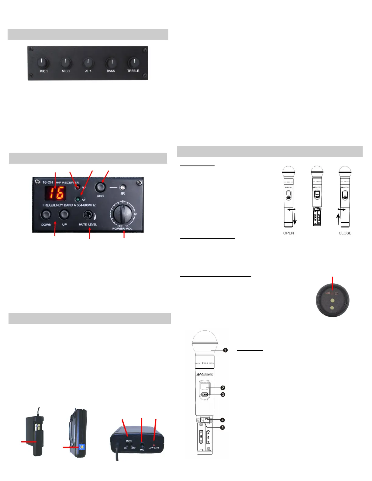
• MIC 1: Adjusts volume level of gooseneck microphone on
reading table.
• MIC 2: Adjusts volume level of microphone plugged into the
MIC 2 input jack on amplifier.
• AUX: Controls output level of device that is plugged into the
L/R RCA jacks.
• BASS: This control cuts or boosts the bass level.
• TREBLE: This control cuts or boosts the treble level.
• Channel Display (A)
• RF - Radio Frequency Indicator (B)
• AF - Audio Frequency Indicator (C)
• ASC / IR Auto Channel Select (Handheld Only) (D)
• Select Buttons - Manual Channel Selection (E)
• Mute Level Adjustment (F)
• Volume Control (G)
J
I
K
H
• The receiver has its own POWER / VOLUME control (G). Turn
Power On. A Frequency Channel will appear in the Channel
Display (A). Press Select Buttons (E) to select a channel.
Channel number must match channel number on wireless
transmitter.
• The TRANSMITTER BODYPACK is operated by 1 - "AA" 1.5 Volt
alkaline battery. Slide off battery cover (H) and install battery
as shown. Make certain the battery is fully seated in its com-
partment so the cover slides in place easily. Battery life with
alkaline batteries is approximately 8 hours of operating time.
CONTROL PANEL
YOUR LECTERN MAY NOT CONTAIN ALL OF THE ELECTRONIC MODULES AS SHOWN AND EXPLAINED HERE.
A
B
C
G
F
E
D
Battery Cover
Channel Selector
Top Panel
L
BATTERIES
Install batteries as follows;
• Hold the body of microphone in
hand and twist off bottom sec-
tion of microphone.
• Insert two “AA” 1.5 V batteries.
• Twist bottom section back on to
microphone.
BATTERY STATUS
The life expectancy of the two batteries is about 10 hours. When the
“BATTERY” symbol on the display screen keeps flashing the batteries
should be replaced immediately.
AUTO SYNC TO RECEIVER
First select channel you wish to use on the receiv-
er. Then press the ASC button (D), the IR light will
start to flash. Turn on microphone and point end
(M) of microphone at the flashing IR light on re-
ceiver and the microphone will auto sync to the
same channel as selected on the receiver.
M
Functions
1) Interchangeable Microphone Head
2) LCD Screen
3) Power / Mute Control Switch
4) Select Button
5) Microphone Input Sensitivity Adjustment—
is used to set the gain of microphone. If you
are a soft talking speaker you will need to turn
the control counter clockwise. Turn clockwise
if you are a loud talker. Use plastic screwdriv-
er that is supplied.
CONTINUED NEXT PAGE
16 CHANNEL WIRELESS RECEIVER
RECEIVER / TRANSMITTER (BODYPACK) SETUP
WIRELESS HANDHELD MICROPHONE—MODEL S1695
 Loading...