Chapter 1 Setting Up the EnCore 420
CoreModule 420 QuickStart Guide 5
CM420QKS_11a
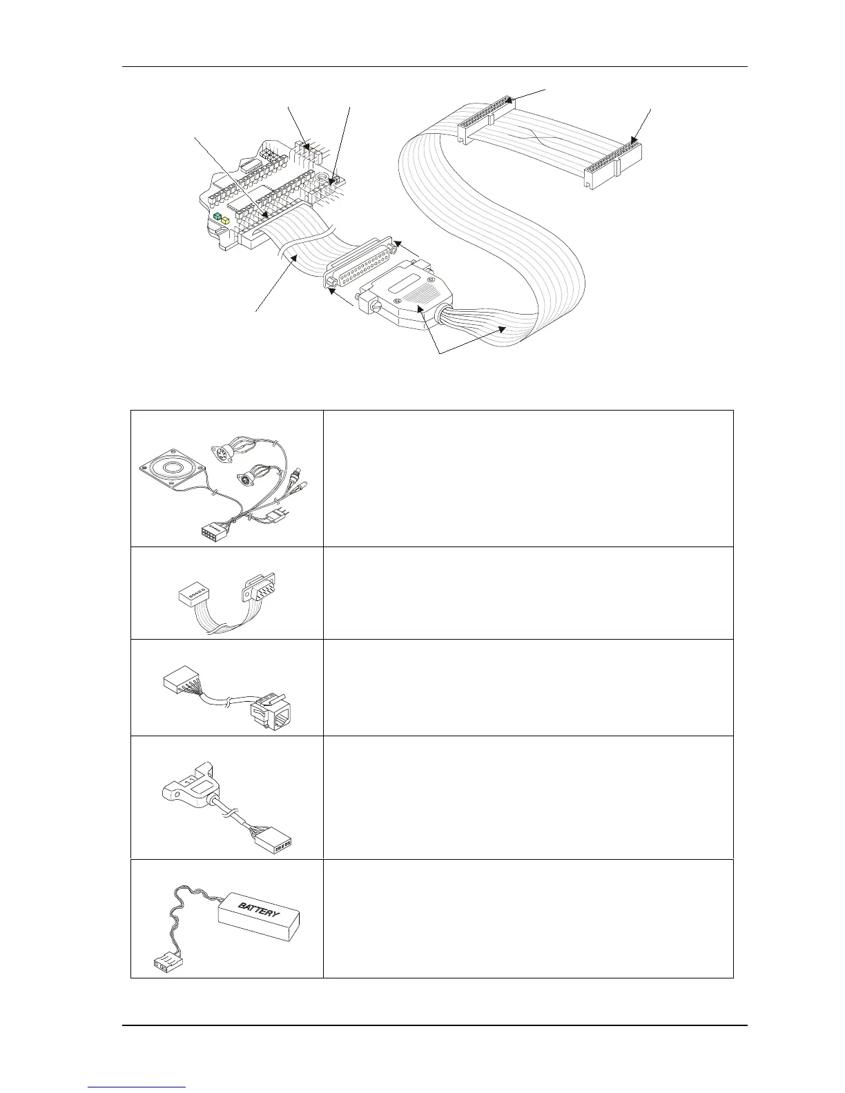
Floppy A (Typical)
Floppy B
Floppy-to-Parallel Adapter Cable
Floppy/Parallel
Cable to (J4)
Utility (J5) Serial 1 (J3)
Floppy/Parallel (J4)
Figure 1-4. Connecting Floppy-to-Parallel Adapter Cable
5) Connect Utility cable The Utility cable is connected to the Utility connector (J5).
See Figures 1-1, 1-2, and 1-5.
6) Connect Serial cables The serial cables are connected to the respective Serial ports (J3, J9,
J13, and J14). See Figures 1-1, 1-2, and 1-5.
All four serial ports use the same type cable for each port (vertical or
right angel).
7) Connect Ethernet cable The Ethernet cable is connected to the Ethernet connector (J2).
See Figures 1-1, 1-2, and 1-5.
8) Connect USB cable
The USB cable is connected to the USB connector (J10).
See Figures 1-1, 1-2, and 1-5.
9) Connect RTC Battery The RTC battery and its cable are connected to the Utility cable
connector to power the RTC. See Figures 1-5 and 1-6.