PAGE 6 XA1000 & XA1400 INSTALLATION AND OPERATION MANUAL
CONTROLS, CONNECTORS & INDICATORS
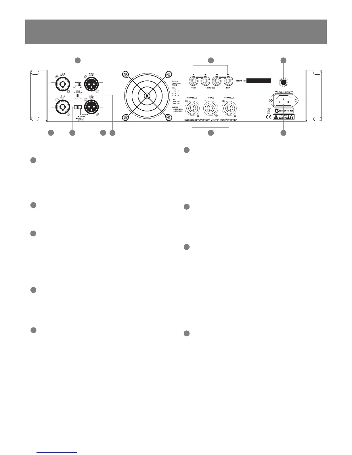
Rear Panel
9
Balanced Input
A female 3-pin combined XLR/TRS type connector is provided on each input:
Pin 1/Sleeve = Signal Ground;
Pin 2/Tip = Hot (non-inverting or in phase);
Pin 3/Ring = Cold (inverting or reverse phase).
9a
Signal Strapping
A male 3-pin XLR type connector is provided and wired in parallel with the
female input XLR for strapping / looping signal between amplifi ers.
10
Signal Ground Lift Switch
When this switch is engaged it disconnects signal ground from the input
connectors on both channels. It is intended to be used when “hum” is caused by
earth loops (due to different ground potentials between source equipment and
the amplifi er) or stray magnetic fi eld pick up on the input ground/shield wiring.
(It does not interrupt signal ground continuity on the strapping connector). The
amplifi er should be turned off before engaging this switch!
11
Binding Post Outputs
Touch proof binding posts (banana jacks) are provided for speaker output
termination with banana plugs or bare wire. The red post is used as positive
and the black post is used as negative. For bridge connection, use only the red
posts.
11a
Speaker Output Connector
A 4 pole speaker connector is provided as an additional speaker output. This
standard of loudspeaker-to-amplifi er connection allows access to both channels
of the amplifi er via the one connector for bi-amp applications. Channel-A is
considered the dominant channel and has both channels wired to the speaker
connector. See the installation section of this manual for detailed information on
speaker connector wiring.
9
10 11
11a
14 9a 15 12
13
12
Mains Connection
Your amplifi er is fi tted with an internationally recognised IEC mains inlet
connector.
Please ensure that the connecting mains lead for use with the IEC connector is
of an approved type and is of suffi cient current carrying ability.
Note: Your unit must always be earthed!
13
Circuit Breaker
The amplifi er is fi tted with a resettable circuit breaker.
If the circuit breaker trips, allow 3 mins for the contacts to reset thermally
before pushing the reset button to reset it mechanically.
14
Stereo/Bridge/Parallel Mono Switch
When set to STEREO, your amplifi er operates as two independant channels.
When set to PARALLEL, your amplifi er will only accept signal applied to Channel
A’s input XLR. Channel B’s output signal will come from A’s input but both
channels will have independant attenuator control.
When set to BRIDGE mode of operation your amplifi er will only accept
signal applied to channel A’s input XLRs and the level of both channels
will be controlled by the channel A attenuator. The output from channel B
will automatically be of the opposite polarity (reversed phase) and speaker
termination should be sourced from the red binding-post outputs. Alternatively,
the speaker could be connected to poles 1+ & 2+ of the 4 pole speaker
connector (see Installation – Output Wiring on page 11).
15
Gain Setting
This switch adjusts the sensitivity of your amplifi er. When set to 0dB a 0dBu
signal applied to the input with the attenuator at max will deliver maximum
power to the output.
 Loading...