OP247 AdapterOP247 Adapter
RS232C
Interface
revision 2.0
FUSE - 2 ampere
3AG FAST BLO
CAGE CODE 1CRL2
PHONE 800-350-5105
MADE IN USA
www.amptec.com
RESEARCH
AMPTEC
MODEL NUMBER 620A4
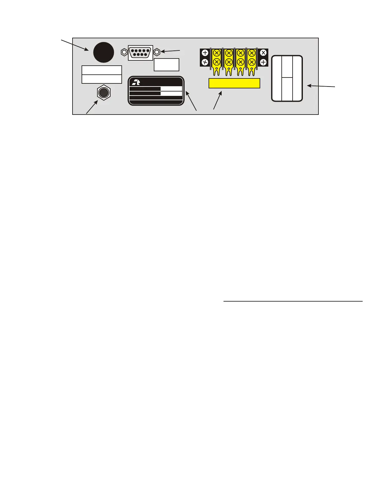
AMPTEC 620A-4 REAR PANEL configured with Option "232" , "247"
(not part of NSN 6625-01-460-1499NM package)
SERIAL NUMBER 620A4-1278
VHI VLO IHI ILOVHI VLO IHI ILO
620A4 Rear Panel with options RS232C I/O
The AMPTEC 620A4 rear panel (shown above) may
contain many optional jacks, terminals, labels, and
stickers. Only the option "247" Continuous Isolated
Operating Power DC Adapter (item #1) plugs in the rear
panel jack for isolation and in order to continuously
operate the unit.
Item 2 is the fuse holder - replace with a 2 ampere 3 AG
type fast blow fuse (rarely needs replacing).
RS232C Serial Interface - Item # 3 is the safety isolated
RS232C serial I/O (9 pin D type Sub-min connector ).
This RS232C Interface provides the meter’s resistance
measurements to a PLC fitted with a serial port. The
RS232C protocal settings should be 9600 Baud, 8 Bits
, No parity , 1 Stop Bit , 9 pin D Sub-min connection.
RS232C Command Set (Option 232 )
(NOTE: All front panel range buttons must be de-
selected (press in half way) with all range pushbuttons
out in order to disable with local lockout and enable
RS232C control. Note commands are case sensitive.
C Continuous Read Mode - RS232C I/O outputs
a data string every A to D conversion cycle, approx. 2.5
times per second.
S Single Read Mode - RS232C I/O outputs a
single data string upon reception of a “R” command.
R Read - Commands RS232C I/O to output a
single data string ( 1 resistance reading).
r0 De-Selects all Ranges
r1 Selects the 20 Ohm Range
r2 Selects the 200 Ohm Range
r3 Selects the 2K Ohm Range
r4 Selects the 20K Ohm Range
V Version commands board to output the firmware
version string.
CERTIFIED BY
DATE
CALIBRATED
DATE DUE
AMPTEC 620A4
23JUNE2004
23JUNE2005
DWH
Serial # 620A4-1278
2
1
4 5
6
3
Data Format - The RS232C I/O outputs a data
string with the following format:
1.2345E+3 The measurement is always in Ohms
+3
(where E+3 = 10 scientific notation style) . The
Exponent is defined below. 1.2345E+3 = 1.2345
+3
+3
KOhms (where E =10 ). 1.3700E+1 = 13.700
+1
+1
Ohms (where E =10 )
Range Exponent
20.0 Ohm E+1
200.0 Ohm E+2
2.0 K Ohm E+3
20 K Ohm E+4
An overrange condition is indicated by
9.9999Enn..Where nn is the selected resistance
range exponent. A Range Error is indicated by
x.xxxxERR.
Item # 4 is the unit’s serial number sticker.
Item # 5 is the gold plated 4 terminal rear terminal
strip (they are wired in parallel with the front termi-
nals). If a “2 wire ohms” connection is made then
the V high and I high terminals should be shorted
together, and the V low and I low terminals should
be shorted. The AMPTEC 620A-4 Voltage High,
Voltage low, Current high and Current low wires
are permanently connected to the gold plated rear
terminal strip ( seel labeled gold plated terminal
strip on rear panel).
Item #6 Calibration Sticker - If the calibration
due date has expired ( 1 year) AMPTEC or a Cal.
Lab can contacted to re-certify the AMPTEC
620A4 Explosive Safety Ohmmeter/Igniter Tester.
contact AMPTEC customer service 001-512-858-
4045 .
 Loading...
