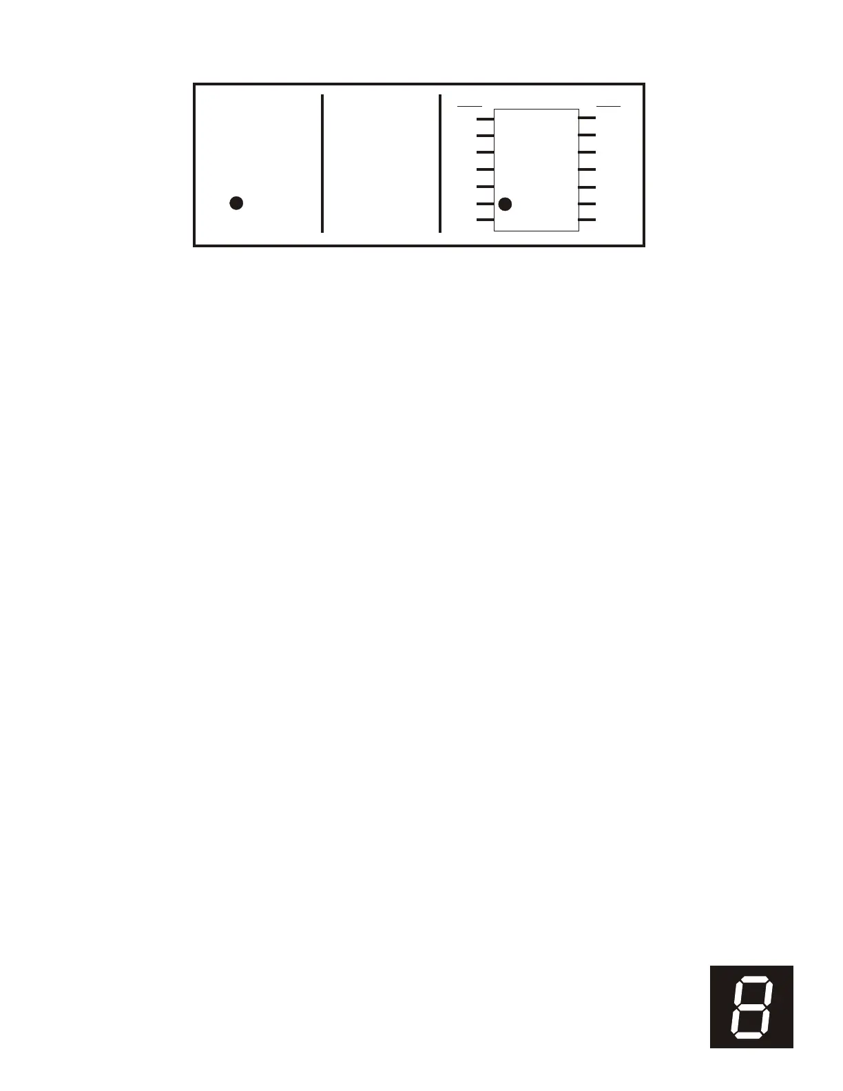
8
A
B
G
F
CE
D
D.P.
SEGMENT PIN
A . . . . . . . . 1
B . . . . . . . . 13
C . . . . . . . . 10
D . . . . . . . . 8
E . . . . . . . . 7
F . . . . . . . . 2
G . . . . . . . . 11
D.P. . . . . . . . . 6
Common . . . . 14
8
PIN
1
2
3
4
5
6
7
PIN
14
13
12
11
10
9
8
Figure E-4. LED Display Pin Functions
E-8. Relay Board General Operation
(Not for NSN 6625-01-460-1499NM meters)
For products such as the ruggedized water-proof
version AMPTEC 620A-4R Igniter Tester and
remote controlled versions via the RS232C
Interface option, the internal 620A-4(R) PCB
labeled “620-relay board” replaces the range
switch S1 on the main board. IC-1 is actually a
ribbon cable header that goes to the top panel
and connects to the range push buttons (covered
by silicone rubber boots) and their correspond-
ing panel mount LEDS. IC-2 is a latch that will
latch its output to the corresponding range push
button input. Its output turns on the front panel
LED (acts as an range mode indicator LED) and
a corresponding relay that connects to the main
PCB to select the range. RL1 is for the 20-Ohm
range, RL2 is for the 200-Ohm range, RL3 is
for the 2K Ohm range, and RL4 is for the 20K
Ohm range.


 To Next Page