720A Operation and Maintenance Manual – Rev S – January 25, 2019
Page 26
13231 Rooster Springs Rd.,
Austin, TX 78737
T: (512) 858-4045 E: info@amptec.com
Precision Standard Resistors Continued:
• One 100 KΩ resistance standard at ± 0.005% or better accuracy
Other Equipment:
• One trimmer potentiometer adjustment tool
• One AMPTEC OP-300 48” gold plated Kelvin clip lead set
• (Optional) One AMPTEC OP-304 48” banana jack calibration lead set
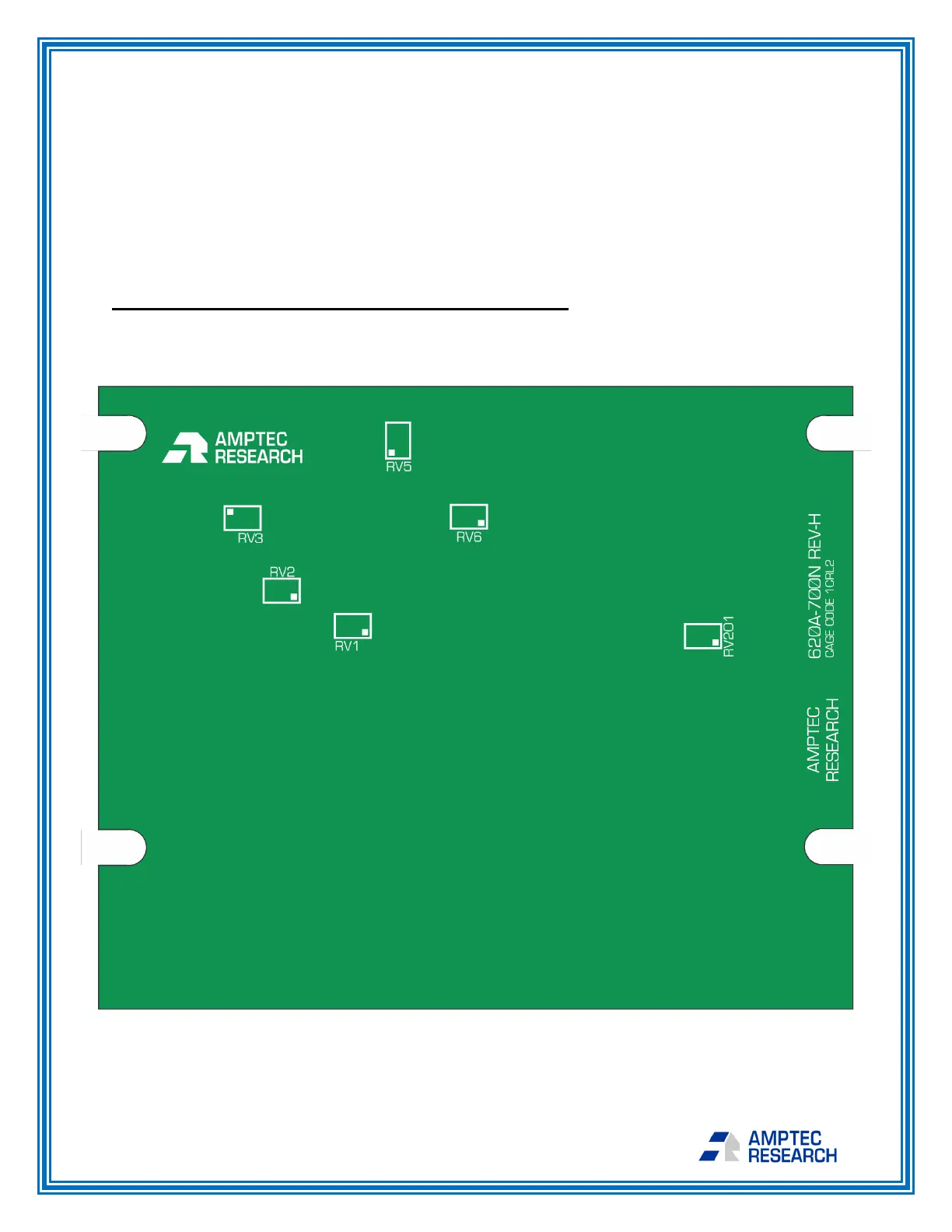
E-4.2 Trimmer Potentiometer Adjustment Locations
The locations of the trimmer potentiometers (referred to as trim pots in this procedure)
that you will adjust during calibration are shown on Figure 9 below. You will be using the
trim pots that are located at RV1, RV2, RV5, and RV6 to calibrate your instrument.
Trim Pot Locations on Main Board of 720A Meter