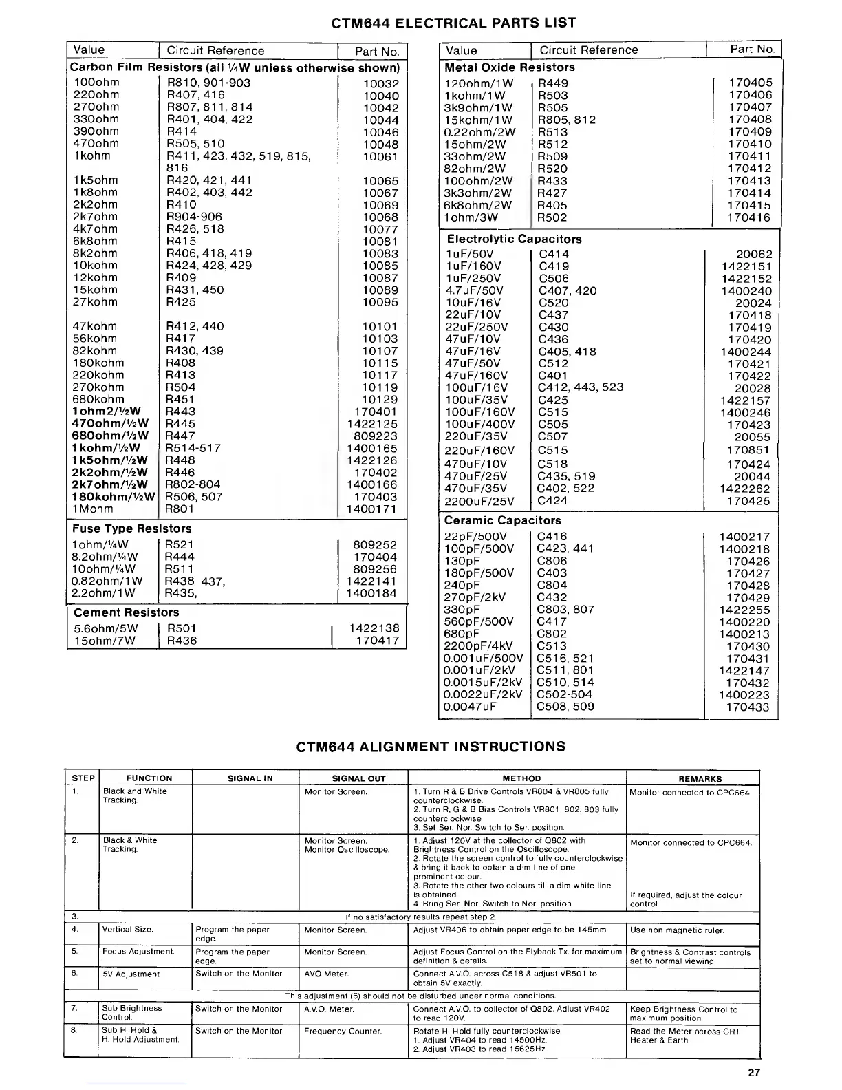
CTM644 ELECTRICAL
PARTS
LIST
Value
Circuit
Reference
Part
No.
Carbon Film
Resistors
(ail
1
AW unless
otherwise
shown)
100ohm
R81 0,901-903
10032
220ohm
R407, 416
10040
270ohm
R807,
811,814
10042
330ohm
R401.404,
422
10044
390ohm
R414
10046
470ohm
R505, 510
10048
1kohm
R41
1,423,
432,
519,
815,
816
10061
1k5ohm
R420, 421,441
10065
1k8ohm
R402,
403,
442
10067
2k2ohm
R410
10069
2k7ohm R904-906
10068
4k7ohm R426, 518
10077
6k8ohm R415
10081
8k2ohm R406,
418,
419
10083
10kohm
R424,
428,
429
10085
12kohm
R409
10087
15kohm
R431.450
10089
27kohm
R425 10095
47kohm R412, 440
10101
56kohm R417
10103
82kohm R430, 439
10107
180kohm R408
10115
220kohm R413 10117
270kohm R504
10119
680kohm
R451 10129
1ohm2/
1
/
2W
R443 170401
470ohm/
1
/2W
R445 1422125
680ohm/y
2
W
R447
809223
1kohm/
1
/
2W R514-517
1400165
1k5ohm/
1
/2W R448
1422126
2k2ohm/y2W R446
170402
2k7ohm/V
2
W R802-804 1400166
180kohm/
1
/
2W
R506,
507 170403
1Mohm R801
1400171
Fuse Type Resistors
lohm/'AW R521
809252
8.2ohm/
1
/4W
R444
170404
lOohm/'AW R511
809256
0.82ohm/1W R438
437,
1422141
2.2ohm/1W R435,
1400184
Cement Resist ors
5.6ohm/5W
R501
1422138
15ohm/7W
R436 170417
Value
Circuit
Reference
Part No.
Metal Oxide
Resistors
120ohm/1W R449
170405
1kohm/1W R503
170406
3k9ohm/1W R505
170407
15kohm/1W R805,
812
170408
0.22ohm/2W
R513
170409
15ohm/2W
R512
170410
33ohm/2W R509
170411
82ohm/2W R520
170412
100ohm/2W R433 170413
3k3ohm/2W R427 170414
6k8ohm/2W R405 170415
1ohm/3W R502 170416
Electrolytic
Capacitors
1uF/50V
C414 20062
1uF/160V
C419 1422151
1uF/250V
C506 1422152
4.7uF/50V
C407, 420
1400240
10uF/16V
C520
20024
22uF/10V
C437
170418
22uF/250V
C430
170419
47uF/10V
C436
170420
47uF/16V
C405,
418
1400244
47uF/50V
C512
170421
47uF/160V
C401
170422
100uF/16V
C412,
443,
523
20028
100uF/35V
C425
1422157
100uF/160V
C515
1400246
100uF/400V
C505
170423
220uF/35V
C507
20055
220uF/160V C515
170851
470uF/10V
C518 170424
470uF/25V
C435, 519
20044
470uF/35V
C402,
522
1422262
2200uF/25V
C424 170425
Ceramic
Capa<
:itors
22pF/500V
C416 1400217
100pF/500V
C423, 441
1400218
130pF C806
170426
180pF/500V
C403
170427
240pF
C804
170428
270pF/2kV
C432
170429
330pF C803, 807
1422255
560pF/500V
C417
1400220
680pF
C802
1400213
2200pF/4kV
C513
170430
0.001 UF/500V
C516, 521
170431
0.001 uF/2kV C51
1,801 1422147
0.001 5uF/2kV
C510,
514
170432
0.0022 uF/2kV
C502-504
1400223
0.0047uF C508, 509
170433
CTM644
ALIGNMENT INSTRUCTIONS
STEP FUNCTION
SIGNAL IN
SIGNAL OUT
METHOD
REMARKS
1. Black and White
Tracking.
Monitor Screen. 1. Turn R & B
Drive Controls VR804
& VR805 fully
counterclockwise.
2. Turn R,
G
& B Bias
Controls
VR801 , 802, 803 fully
counterclockwise.
3. Set
Ser. Nor. Switch
to
Sen position.
Monitor
connected
to CPC664.
2.
Black
& White
Tracking.
Monitor Screen.
Monitor Oscilloscope.
1
.
Adjust 1 20V at the collector of Q802 with
Brightness Control on the Oscilloscope.
2. Rotate the screen control to fully counterclockwise
&
bring it back to obtain a dim line of one
prominent colour.
3. Rotate the other two
colours till
a
dim
white line
is obtained.
4. Bring Ser. Nor. Switch to
Nor. position.
Monitor
connected to CPC664.
If required,
adjust
the colour
control.
3.
If
no
satisfactory results repeat step 2.
4. Vertical
Size. Program the
paper
edge.
Monitor Screen. Adjust
VR406 to obtain paper edge to be 145mm.
Use non magnetic
ruler.
5. Focus
Adjustment.
Program the paper
edge.
Monitor Screen. Adjust
Focus Control on the Flyback Tx. for maximum
definition
&
details.
Brightness
& Contrast
controls
set to normal viewing.
6.
5V Adjustment
Switch on the Monitor.
AVO Meter. Connect A.V.O.
across
C518 &
adjust VR501
to
obtain 5V
exactly.
This
adjustment
(6)
should not be
disturbed under normal
conditions.
7.
Sub Brightness
Control.
Switch on
the Monitor.
A.V.O. Meter. Connect
A.V.O. to collector
of
Q802.
Adjust
VR402
to
read 1 20V.
Keep
Brightness
Control
to
maximum
position.
8.
Sub H. Hold&
H.
Hold Adjustment.
Switch
on the Monitor.
Frequency Counter. Rotate H.
Hold fully counterclockwise.
1.
Adjust
VR404 to read
14500Hz.
2. Adjust
VR403 to read 1
5625Hz.
Read the Meter
across
CRT
Heater
& Earth.
27