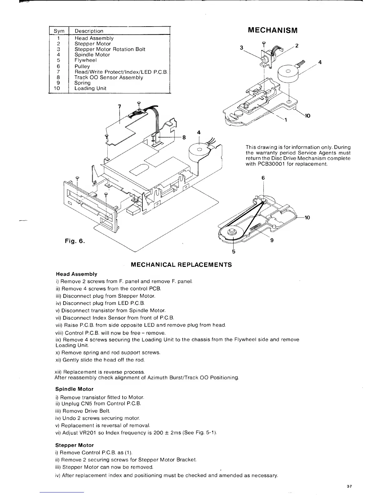
Sym Description
1 Head Assembly
2 Stepper Motor
O
Stepper Motor Rotation Bolt
4
Spindle
Motor
5
Flywheel
6 Pulley
7 Read/Write
Protect/lndex/LED
P.C.B.
8
Track
OO Sensor Assembly
9
Spring
10 Loading Unit
MECHANISM
This drawing is for information only. During
the warranty period Service
Agents must
return the Disc Drive Mechanism complete
with PCB30001 for replacement.
Fig.
6
MECHANICAL REPLACEMENTS
Head Assembly
Remove 2
screws from F. panel and remove F. panel.
i)
Remove 4 screws from the control PCB.
ii) Disconnect plug from Stepper Motor.
v)
Disconnect plug from LED P.C.B.
v) Disconnect transistor from
Spindle Motor.
vi) Disconnect Index Sensor
from front of P.C.B.
vii)
Raise P.C.B.
from side opposite LED and remove
plug from head.
viii) Control P.C.B. will now
be
free
-
remove.
ix) Remove 4 screws securing
the Loading Unit to the
chassis from the Flywheel side and remove
Loading
Unit.
x) Remove spring and rod
support screws.
xi) Gently slide
the head off the rod.
xii) Replacement is
reverse process.
After
reassembly check alignment of Azimuth Burst/Track OO Positioning.
Spindle Motor
)
Remove
transistor fitted to
Motor,
i) Unplug
CN5
from Control P.C.B.
ii) Remove Drive
Belt,
v)
Undo
2 screws securing
motor,
v) Replacement is
reversal of removal,
vi) Adjust VR201 so
Index frequency is 200 ± 2ms (See
Fig,
5-1).
Stepper Motor
)
Remove Control P.C.B. as
(1).
i) Remove 2 securing screws for
Stepper Motor Bracket.
ii) Stepper Motor can now
be
removed.
v) After replacement
index
and positioning must
be
checked and amended
as
necessary.