For full warranty information, refer to the AMX Instruction Manual(s) associated with your Product(s).
06/01/2015
©2015 AMX. All rights reserved. AMX and the AMX logo are registered trademarks of AMX.
AMX reserves the right to alter specifications without notice at any time.
AMX by HARMAN - 3000 RESEARCH DRIVE, RICHARDSON, TX 75082 • 800.222.0193 • fax 469.624.7153 • technical support 800.932.6993 • www.amx.com
AMX (UK) LTD, AMX by HARMAN - Auster Road, Clifton Moor, York, YO30 4GD United Kingdom • +44 1904-343-100 • www.amx.com/eu/
2. Plug the other ends of the power cords into power sources.
3. Turn on the power strip and wait 30 seconds.
4. Check the Indicator LEDs on front and rear of the enclosure; see table below.
5. For systems with boards that require modules – Apply power to the modules.
6. Apply power to the source and destination devices.
If indicator lights do not respond with a normal display as stated in the table below, check
power connections and see the troubleshooting information in the manual before
contacting technical support.
Executing a Test Switch with the Control Panel
The Enova DGX Control Panel (standard on all enclosures) is used for controlling the
system’s switches and system attributes.
Control Panel Keys and Dial
• Function Key – Press for start of the Function menu anytime during operation.
• Select Key – Press to enter selections.
• Cancel Key – Press to cancel an incomplete operation.
• Take Key – Press to complete an operation.
• Control Dial – Turn to scroll through the Function menu (starts with Change for
switching). After scrolling past the last item, menu loops back to the first item.
To execute a test switch:
1. From the Function menu, locate Disconnect by scrolling with the Control Dial and
then press the Select Key.
2. Press Input Key 1; press the Take Key.
The default switch of 1 to all is disconnected.
3. Press the Function Key; press the Select Key to select Change.
The available Input and Output Keys turn blue.
4. Press Input Key 1. Input Key 1 flashes white.
5. Press Output Key 1. Output Key 1 illuminates white.
6. Press the Take Key to execute the switch. Both keys turn blue.
After the test switch, attach the remaining sources and destinations. For products that
require transmitters or receivers, install appropriate modules between the boards and the
devices.
Establishing a LAN Connection
The Enova DGX Switcher has an integrated NetLinx Central Control Processor with the
server connection via the LAN 100/1000 port on the CPU.
Important: (1) Enova DGX Switchers use DHCP by default. (2) Do not
connect the
LAN 100/1000 port on the Enova DGX Switcher directly to a PC. It will not
work.
Cable Requirements for the LAN Connection
Connect the LAN port on the Enova DGX Switcher directly to a LAN (network) with an
RJ-45 cable (crossover or straight-through; port automatically adjusts). A DHCP capable
server must be in the network.
To connect an Enova DGX Switcher to a LAN:
1. If the system is not already powered, apply power according to the directions in the
right-hand column on the first page.
2. Insert one end of an RJ-45 link cable into the LAN 100/1000 port.
3. Connect the other end of the RJ-45 link cable to a LAN hub or switch.
The network will automatically assign a DHCP IP address.
4. Check the indicator LEDs on the LAN 100/1000 port (FIG. 5 right).
Note: The Program port is used for NetLinx Studio setup.
Important: The RJ-45 connectors on the far left of the CPU should only be used to
connect to autonomous devices to prevent network loops (linking of enclosures is not
allowed).
For additional details on setup of the NetLinx Master via the WebConsole and control via
the integrated NetLinx Central Control Processor, see the Instruction Manual.
Establishing Serial Control (if applicable)
An Enova DGX Switcher can also be controlled by attaching an external control device/
system to the Control (RS-232) port.
PC Requirements for BCS commands* via a terminal emulation program:
• Windows 7
®
or Windows XP Professional
®
• Serial port (or USB port – see the Instruction Manual)
* Complete BCS information can be found in the Instruction Manual – BCS (Basic Control
Structure) Protocol at www.amx.com
.
To establish external control from RS-232 serial port:
1. If the system is not already powered, apply power according to the directions in the
right-hand column on the first page.
2. Plug the null modem serial cable into the serial port on the enclosure (FIG. 6).
3. Plug the other cable end into the serial port on the serial controller/device (PC).
4. Open the serial communication software and set the port settings on the PC to
match the Enova DGX Switcher default settings (baud rate = 9600, data bits = 8,
stop bit = 1, parity = none, and flow control = none).
External Serial Control via BCS – Test Switch
BCS Commands – Open a terminal emulation program on the PC. When power is
applied to the enclosure, a short splash screen appears. Enter DI1T (clears default
switch of 1 to all). Enter CI1O2T (routes Input 1 to Output 2 on default level). When
CI1O2T appears, the switch is successful.
Additional Information Covered in Instruction Manual
See the Instruction Manual – Enova DGX 8/16/32/64 Digital Media Switchers at
www.amx.com
for information on the following:
• NetLinx programming and firmware upgrades
• Complete control panel operation
• DGX Configuration Software with Scaler and EDID Programmer functionality,
a terminal emulation view, and the ability to enable or disable HDCP
• Setup for complete power redundancy with redundant power supplies
• Managing configuration files with XNConnect
• Adding or replacing boards
• APDiagnostics software (monitors and displays advanced diagnostic data)
• Programmer’s interface for system diagnostics; DGX_SHELL commands
Reference Documents
• Instruction Manual – DXLink Fiber Transmitters and Receivers
• Instruction Manual – DXLink Twisted Pair Transmitters/Receiver
• Cabling for Success with DXLink (on DXLink Twisted Pair product pages)
• Instruction Manual – DGX Transmitters & Receivers
• WebConsole & Programming Guide – NX-Series Controllers
• Instruction Manual – BCS (Basic Control Structure) Protocol
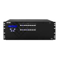
FIG. 3
Power cords must be plugged into all power receptacles (Enova DGX 64 shown)
Indicator LEDs – Normal Display on Power Up
Front Panel Power – power status Green (when all power supplies are working)
Power Supplies
(DC is Tri-color)
AC power
Green
• DC power
• Temperature
• Fault status
Green (amber = over temperature; red = fault state)
CPU Status – system status
• Green during boot up (depending on load,
approximately 10 to 30 seconds)
• Blinking green at 1 second intervals when ready
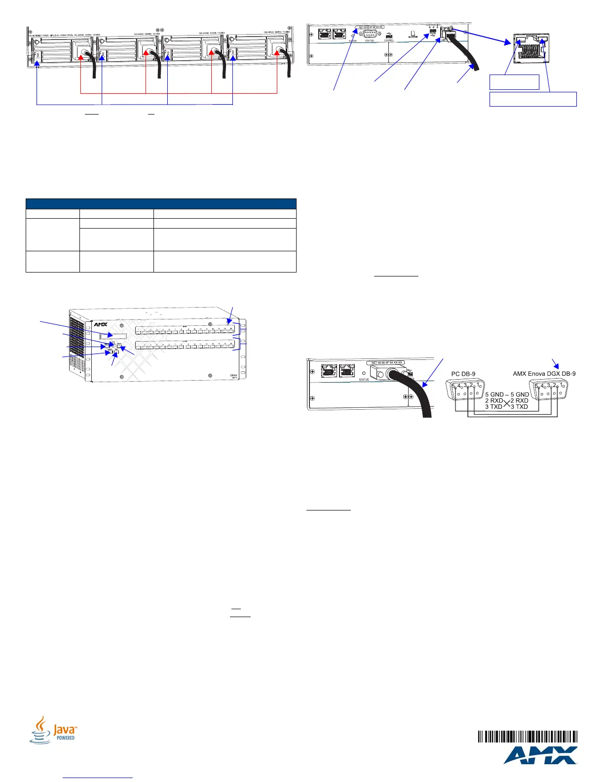
FIG. 4 Front view with control panel (Enova DGX 16 shown)
Power cords
Power indicators
Function Key
Control Dial
Select Key
LCD
Cancel Key
Take Key
Output Keys
Input Keys
Power Indicator
FIG. 5 LAN 100/1000 (RJ-45) port and Indicator LEDs
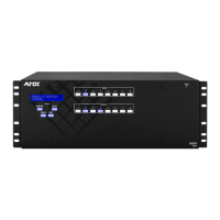
FIG. 6 Null modem serial cable connected to Control (DB-9) serial port
LAN 100/1000 (RJ-45) port
Program port
To LAN
LAN 100/1000 LEDs
L/A LED (green):
Active connection
SPD LED (yellow):
Receiving/transmitting LAN data
MAC address
Null modem serial cable and pinout
 Loading...