16
OPER
ATIONS TO BE PERFORMED WHEN
SUBSTITUTING
THE INJECTORS
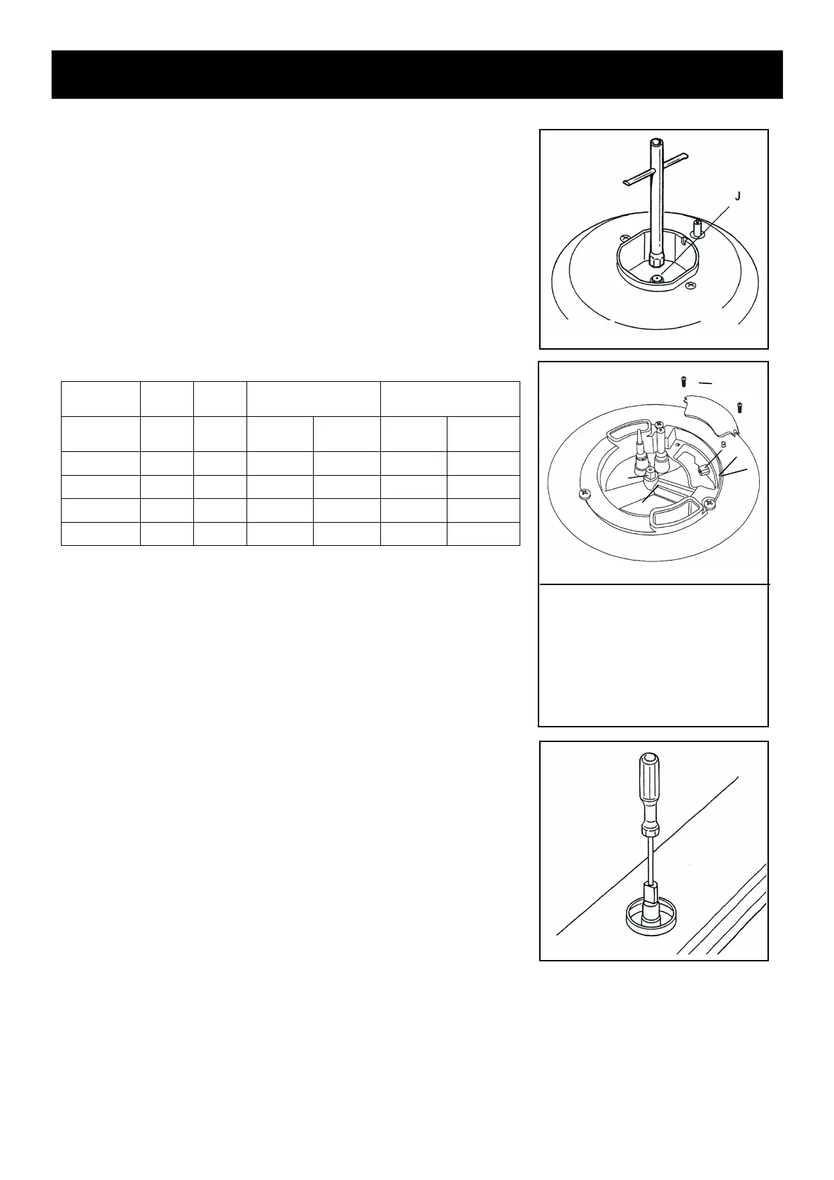
• Remove the gratings, the burner covers and the knobs;
• Using a wrench substitute the nozzle injectors “J” (fig: 5.4 - 5.5)
with those most suitable for the kind of
gas for which it is to be
used.
The
burner are conceived in such a way so as not to require the
regulation of the primary air.
fig. 5.4
INJECTORS TABLE
REGULATING THE BURNER MINIMUM SETTING
When switching from one type of gas to another, the minimum flow
rate
must also be correct: the flame should not go out even when
passing suddenly from maximum to minimum flame.
To regulate the ‘flame follow the instructions below:
• Light the
burner
• Set the
gas valve to minimum
On
gas valves provided with adjustment screw in the centre of the
shaft
(fig. 5.6) Using a screwdriver with max. diameter 3 mm, turn
the scr
ew inside the tap until the correct setting is obtained.
For LP/PROPANE gas, tighten the adjustment screw completely.
After
regulation repeat the operations indicated in paragraph “2.
Pressure r
egulator” at page 12.
If
the cooktop has been disconnected and then connected again to
the
gas supply line repeat the operations indicated in paragraph “5.
Leak Testing” at page 14.
TOOLS NEEDED
A =
T-handle wrench
B = wrench
C = scr
ewdriver
A
J
B
J
C
NOMINAL
POWER
REDUCED
POWER
LP/PROPANE
10
’’ W.C.P.
NATURAL GAS
5’’ W.C.P.
BURNERS BTU/hr BTU/hr
∅ injector
(1/100 mm)
By-pass
(1/100 mm)
∅ injector
(1/100 mm)
By-pass
(1/100 mm)
Auxiliary (A) 3500 800 56 34 82 adjustable
Semirapid (SR)
6000 1300 72 34 114 adjustable
Rapid (R) 10500 1700 98 43 150 adjustable
Triple burner (TC)
15000 5000 105+50 68 165+75 adjustable
fig. 5.5
fi
g. 5.
6
Save the orifices removed from the appliance for the future use