Do you have a question about the Anderic RR7096T and is the answer not in the manual?
Turn off power, remove canopy, disconnect wiring, tuck wires, lay antenna, and reinstall canopy.
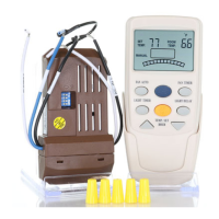
Connect the receiver wires (Green, Red, White, Blue) to the fan and junction box wires.
Note the dip-switch pattern on the receiver for pairing with the remote.
Set identical dip switch patterns on both the remote and receiver for proper communication.
Install batteries into the remote and toggle Fahrenheit/Celsius units.
Control fan speed manually or enable auto mode based on temperature settings.
Set timers for fan/light and adjust temperature settings using hour keys.
Reverse fan direction and control light functions like ON/OFF, dimming, and delay.
This document provides installation and operating instructions for the Anderic® RR7096T, RR7096TR, and UC7067FCRX Receiver. These devices are designed to control ceiling fans and their integrated lights.
The RR7096T and RR7096TR are remote controls, while the UC7067FCRX is a receiver unit that installs within the ceiling fan canopy. The system allows users to control fan speed, light on/off, light dimming, and in the case of the RR7096TR, fan reverse direction. The RR7096T remote does not operate the fan forward/reverse; for fan reverse operation with this remote, the fan must be stopped, and the reverse switch on the fan body manually changed. The RR7096TR remote, however, includes a dedicated "FAN/REV KEY" for this purpose.
The system also features an "FAN AUTO KEY" which allows the fan speed to adjust automatically based on a user-set temperature. This intelligent feature helps maintain a comfortable environment by varying fan speed according to the room's temperature relative to the desired setting.
The system utilizes a receiver unit (UC7067FCRX) that connects to the fan's wiring and the household's electrical supply. The remote controls (RR7096T/RR7096TR) communicate wirelessly with the receiver.
Wiring Connections (UC7067FCRX Receiver):
Power Source for Remote:
Code Combinations:
Fan Control:
Light Control:
Timer Function (RR7096T only):
Temperature Display Toggle:
Battery Replacement:
Pairing with Remote:
Installation:
Troubleshooting: