2
Interior
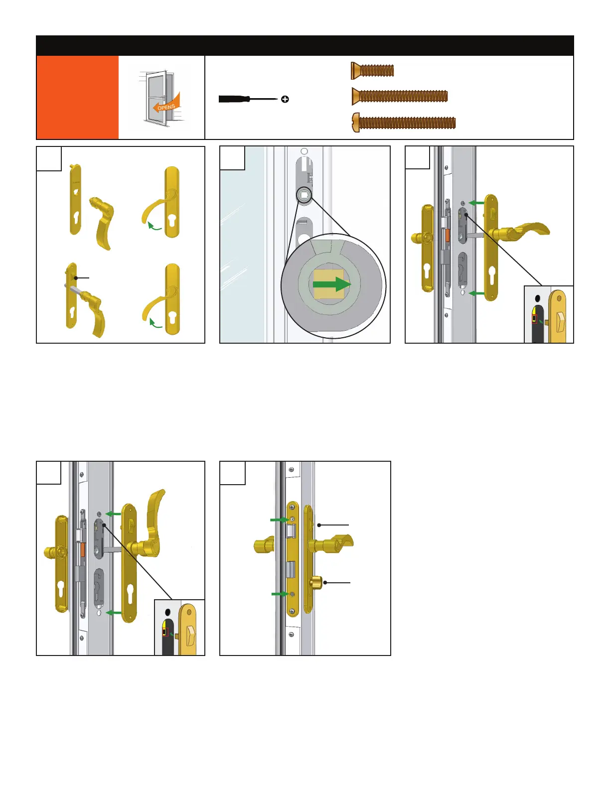
1. Check orientation of the lock case by
looking into the handle holes.
2. If notch is facing away from the glass
panel as seen above, proceed to Step C1.
3. If the notch is pointed downwards, proceed
to Step C2.
1. Rotate the handles into a vertical position.
2. Install exterior and interior trim plates
together using two 1 1/2" pan head
screws onto the door. Spindle will pass
through the square hole in the lock case
and into the other handle.
3. Rotate handle to a horizontal position.
1. Insert handle without spindle into
exterior trim plate (with Andersen logo)
in downward position and rotate slightly
to secure it.
2. Repeat for other handle and interior trim
plate.
Interior
Exterior
D
A
B
Interior
NOTE: Trim plates should not be installed
on door while completing below steps.
1. Rotate the handles into a horizontal
position.
2. Install exterior and interior trim plates
together using two 1 1/2" pan head
screws onto the door. Spindle will pass
through the square hole in the lock case
and into the other handle.
3. Proceed to Step D.
C1
2
Slider
1
Exterior
Interior
2
2
C2
STOP: Laminated Fixed Glass Doors only.
Slider must be replaced. See Interior Trim
Plate Kit for further instruction.
Slider
1. Install lock case trim plate onto the edge
of the door and fasten with one 5/8”
screw. Do not overtighten.
2. Insert dead bolt key cylinder into lock
case. Turn thumb latch to ensure proper
installation. Fasten with one 1 1/2”
athead screw. Do not overtighten.
NOTE: Slider feature will function only on
doors featuring Quick Change System.
Dead
bolt key
cylinder
with thumb
latch
TOOLS NEEDED
STEP 1: INSTALL HANDLE SET
RIGHT
HANDED
!
!
1/2”
1/2”
1/2”
1”
1 1/2”
2”
1 1/2”
5/8”
5/8”
5/8”
x 2 Pan head screws
1 1/2”
#8
#10
#12
#6
3/4” Machine Pan Painted
1/2” SMS Pan
1/2” SMS Pan Painted
1/2” SMS Flathead
1/2” Self-Drill Pan
1/2” Self-Drill Pan Painted
3/4” Machine Flathead
7/8” Machine Pan Painted
1” SMS Pan
1” SMS Pan Painted
1” Machine Pan Painted
1-1/2” Machine Flathead
1-1/2” Machine Flathead
2” SMS Pan Painted
5/8” SMS Pan Painted
1-1/4” SMS Pan
Flathead screw
1 1/2”

 Loading...