
M
Maria WilliamsSep 8, 2025
What to do if coil current is outside the tolerance in ANDERSON-NEGELE IZMAG?
- SStephanie CarterSep 8, 2025
Replace the converter of your ANDERSON-NEGELE Measuring Instruments.
What to do if coil current is outside the tolerance in ANDERSON-NEGELE IZMAG?
Replace the converter of your ANDERSON-NEGELE Measuring Instruments.
What to do if the pulse output of the output channel IMP1 is exceeded in ANDERSON-NEGELE IZMAG Measuring Instruments?
If the pulse output of the output channel IMP1 is exceeded on your ANDERSON-NEGELE Measuring Instruments, adapt the flow rate or reduce the pulse value “pv1”.
What to do if the pulse output of the output channel IMP2 is exceeded in ANDERSON-NEGELE IZMAG Measuring Instruments?
If the pulse output of the output channel IMP2 is exceeded on your ANDERSON-NEGELE Measuring Instruments, adapt the flow rate or reduce the pulse value “pv2”.
How to fix signal overflow in ANDERSON-NEGELE IZMAG Measuring Instruments?
If you're experiencing a signal overflow within the electronic unit of your ANDERSON-NEGELE Measuring Instruments, it could be due to a high flow rate (greater than 12 m/s), electrical influences from an empty meter tube, or defective electronics. To address this: * Check the flow rate. * If the meter tube is empty, perform a check with short-circuited electrodes.
What to do if there is flow without flow rate indication and the conductivity of the liquid is below 50 µS/cm in ANDERSON-NEGELE IZMAG Measuring Instruments?
If you observe flow without flow rate indication on your ANDERSON-NEGELE Measuring Instruments and the conductivity of the liquid is below 50 µS/cm, check whether the display shows “0 gal/min” while the flow is running.
What to do if reference voltage is outside the tolerance in ANDERSON-NEGELE IZMAG Measuring Instruments?
Replace the converter of your ANDERSON-NEGELE Measuring Instruments.
What to do if parameters of the transmitter cannot be saved in ANDERSON-NEGELE Measuring Instruments?
Replace the converter of your ANDERSON-NEGELE Measuring Instruments.
What to do if reference voltage is missing in ANDERSON-NEGELE IZMAG Measuring Instruments?
Replace the converter of your ANDERSON-NEGELE Measuring Instruments.
What to do if base parameters for the measurement are faulty due to a checksum error in ANDERSON-NEGELE Measuring Instruments?
Replace the converter of your ANDERSON-NEGELE Measuring Instruments.
What to do if the pulse value “pv2“”set for the counting output IMP2 is too high (>1000 Hz) in ANDERSON-NEGELE IZMAG Measuring Instruments?
If the pulse value “pv2” set for the counting output IMP2 is too high ( >1000 Hz) on your ANDERSON-NEGELE Measuring Instruments, reduce the pulse value “pv2“.
Introduction to manual, copyright, liability, and safety adherence.
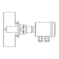
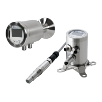
Details available IZMAG versions (integral/remote) and device identification.
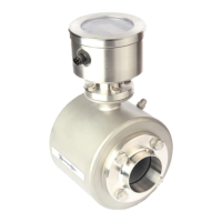
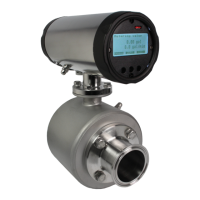
Explains how the IZMAG Electromagnetic Flow Meter measures flow rate and volume.
Technical specifications for the IZMAG converter, including power, outputs, and temperature.
Technical specifications for the IZMAG transmitter, covering connections, materials, and operating limits.
Table detailing total measuring range, flow rate at 1 m/s, and tolerance for sizes.
Highlights user responsibilities for safe operation and adherence to manual instructions.
Essential safety guidelines to prevent endangerment, damage, or faulty batches.
Defines specific applications and liquid types for the IZMAG flow meter.
Explanation of various safety symbols to ensure proper understanding of hazards and precautions.
Guidelines for safe transport, including handling, packing, and labeling requirements.
Table and diagram showing dimensions (D, H, L1, L2) and weights for flowtube sizes.
Specifies requirements for transmitter installation, including voltage, access, and protection.
Instrument is for liquids; solids impact and pipe diameter choice.
Details fitting position, horizontal arrangement, and 3-A mounting rules.
Recommends inlet (5xDN) and outlet (3xDN) pipe sections for accuracy.
Specifies minimum conductivity requirements (>=5 µS/cm) for liquids.
Emphasizes ideal earthing/grounding (resistance <10 Ω) for reliable measurement.
Warns about damaged PFA lining and advises against negative pressure installation.
Explains calibrated flow direction indicator and measurement accuracy.
Precautions for converter installation: temperature, housing integrity, and moisture.
Safety guidelines for transmitter installation, including tightening and earthing.
Converter location, protection from sunlight, and electrical connection precautions.
Safety precautions for electrical installation, referencing standards like ANSI/NFPA 70.
Precautions for converter location: temperature, vibration, sunlight, and electromagnetic fields.
Lists digital outputs, digital input, analog output, and CS3-Bus interface.
Hardware, voltage, current, and frequency for digital pulse output.
Hardware, voltage, resistance, frequency, and function for digital input.
Specifications for analog output: mode, load, and error.
Details CS3-Bus specifications: hardware, protocol, baud rate, and cable.
RJ45 connector for Ethernet IP, parameter modification via web pages.
Specifies Ethernet IP communication types: network, servers, and speed.
Instructions for setting IP address and connecting meter to network.
Defines IZMAG's data exchange structure: input/output data, format, and content.
States that only trained, authorized personnel should operate the device.
Prerequisites for safe commissioning: installation, electrical connection, housing closure.
Steps for startup: pipeline install, flow direction, and zero adjustment.
Confirms device is factory-adjusted with standard settings.
Explains flow measurement in both directions and main flow indicator.
Recommends zero point adjustment for site adaptation upon first startup.
Describes external measurement interruption using digital input IN1.
Explains measurement suppression options for empty meter tubes.
Advises switching off 'EMPTY pipe detection' for conductivities below 50 µS/cm.
Explains connecting AndersonCS3 systems via the BUS interface.
Describes functions of the three optical keys and image navigator control.
Explains display division into main/sub-images and navigator functions.
Presents a flowchart illustrating the IZMAG's operational structure and parameter connections.
Explains how to reset the volume counter to zero using the 'ZERO' key.
Indicates malfunction messages can be deleted by resetting the volume counter.
Describes changing numerical and selected parameters, including unlocking.
Explains releasing parameter changes via code numbers and display feedback.
Details releasing service functions using code numbers and display feedback.
Shows volume display and how to reset it to zero.
Illustrates flow rate display and notes digit size dependency.
Introduces 'Base parameters' for basic device settings.
Explains changing device language, possibly requiring unlock code.
Details changing the CS3-Bus address, possibly requiring unlock code.
Describes changing measurement units and provides a conversion table.
Explains adjusting the Profibus address.
Details parameter modes controlling access and unlocking.
Introduces 'Pulse output' for setting pulse output configuration.
Explains changing pulse mode and lists available modes.
Details changing pulse value PV1, valid for specific modes.
Explains changing pulse length TP1 and its validity.
Details changing pulse value PV2, valid for specific modes.
Explains changing pulse length TP2 and its validity.
Introduces 'Digital input' for setting digital input function.
Describes selecting digital input function (No function, Interruption, Zero setting).
Explains changing IT1, determining signal duration for function activation.
Introduces 'Current output' for configuring current output settings.
Details changing current output mode and available ranges.
Explains changing Qmax, the 20 mA point for current output.
Describes changing time delay TP3 affecting current output.
Explains changing low-flow suppression percentage.
Details changing dimensionless factor MSPE.
Explains changing dimensionless offset BSPE.
Describes changing average value for flow signal filtering.
Explains changing Offset value, a sensor calibration value.
Details changing SPAN value, a sensor calibration value.
Explains switching 'Pipe Detect' function on and off.
Introduces 'Special functions' for operations.
Details 'Zero adjust' measurement and prerequisites.
Explains resetting all parameters to factory settings.
Introduces 'Service level' for service values and functions.
Explains self-monitoring and interpreting error messages via display.
Details error messages for measurement or OS on service level.
Provides error numbers, diagnoses, and remedial actions.
Lists common effects/sources and how to identify them.
Troubleshooting for no flow rate, checking conductivity and empty pipe detection.
Troubleshooting for no pulse, checking circuit, polarity, and parameters.
Diagnosing analog signal issues: disconnecting system, using simulation.
Diagnosing deviations considering time, repairs, and system modifications.
Explains resetting error messages via zero reset or automatically.
Describes visual checks for transmitter: humidity and PFA liner.
Crucial safety instructions for personnel, emphasizing personal safety and equipment handling.
Recommends maintenance steps: cleaning, seal replacement, accuracy tests.
Outlines preventive steps to avert danger, maintain quality, and ensure longevity.
Notes periodic seal replacement and the need for accuracy tests.
Conditions for sending unit for repair: packing and RMA.
Restricts repairs to skilled personnel; advises against component replacement in situ.
Ensures pipe system is empty/unpressurized before transmitter replacement.
Introduces functions for troubleshooting, adjustment, and verification.
Explains simulating flow for diagnosis/adjustment without product.
Describes using 'SIMULATION' function for analog output and pulse generation.
Lists necessary details for spare parts orders and application variations.
Instructions for temporary shutdown, including pipe system emptying.
Advises on proper disposal of defective components according to regulations.
Defines product warranty against defects in materials and workmanship for one year.
Outlines liability limits, user responsibilities, and void conditions.
Specifies the process for returning products for repair or replacement.
| Measuring Principle | Piezoresistive |
|---|---|
| Protection Class | IP67 |
| Output Signal | 4…20 mA / HART |
| Housing Material | Stainless steel (AISI 316L) |
| Operating Temperature | -20°C to +85°C |