8 of 15
VS-CUBE-MANUAL-REV0.1
4.3 Remote Operations (Continued)
For pump models equipped with remote start/stop, this feature
operates by receiving a dry contact signal and is intended to be
connected to a dry contact switch. The input has no polarity. No
voltage is permitted on the input signal. The pump will activate and
run while the switch is closed and deactivate and stop when the
switch opens.
To activate this feature, install the pair of wires from the dry
contact switch closure device into the terminal block (Figure 3).
Set the 3-way rocker in the “right” position to place the pump in EXTERNAL/
AUX mode. The pump will now operate only when receiving a closed contact
signal. To return to local control, move the rocker switch to the “left” or Internal
control position.
Figure 3
Remote Start/Stop
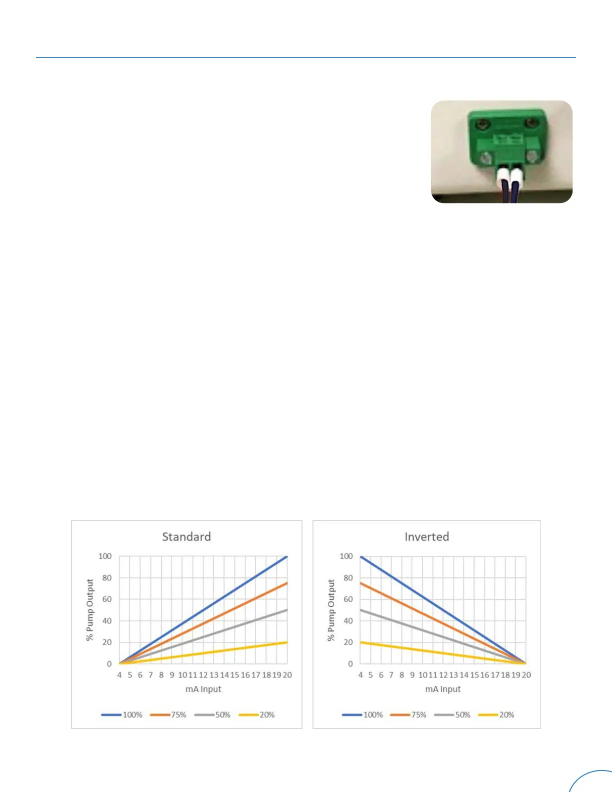
For models equipped with a 4-20mA feature, the pump’s output will vary according to the level of
an incoming 4-20mA analog signal. The pump’s maximum output to the signal is scalable between
20% and 100%, as determined by the percentage setting on the potentiometer.
For
standard signal
models, the minimum output is approximately 5.0% at 4.8mA and increases in
1.0% increments for every .16mA until 100% of the scaled output (based upon the potentiometer
setting) is reached at 20.0mA (Figure 4).
For
inverted signal
models, the maximum output (as established by the potentiometer setting) is
reached at 4.8mA and decreases, as above, until reaching zero output at 20.0mA (Figure 5).
4-20mA Control
Figure 4
Figure 5
NOTE - Loop voltage for all models may not exceed 36VDC.
 Loading...