PAGE 1
CHECKFIRE 210 Detection and Actuation
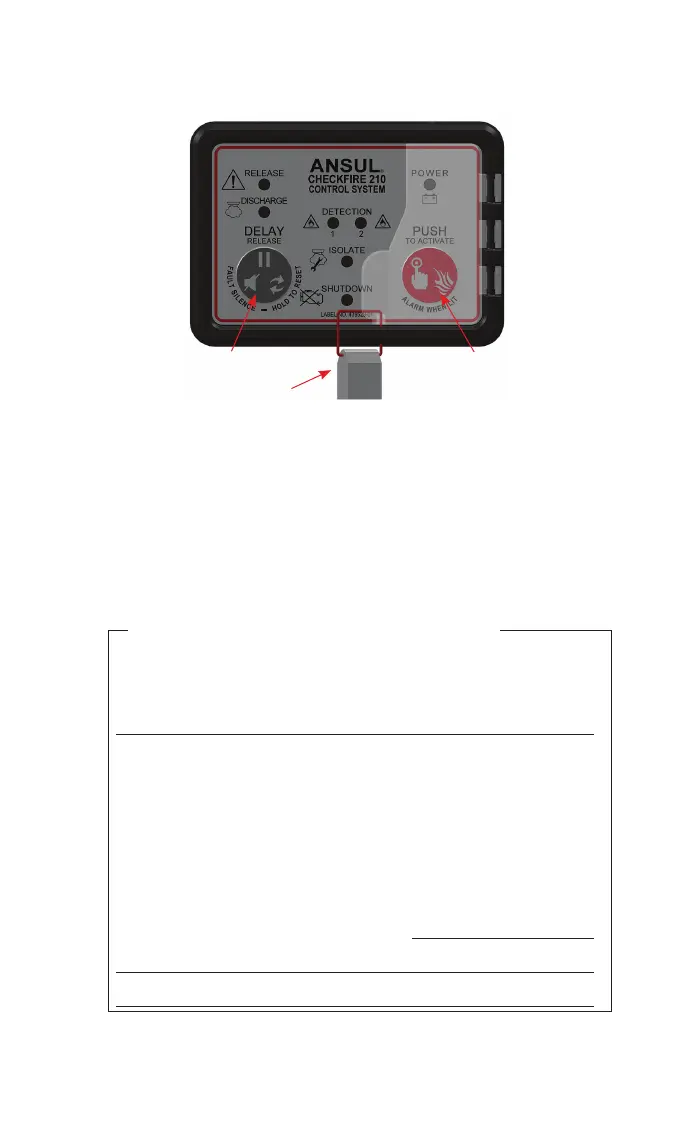
System Owners’ Guide
“DELAY/RESET/
SILENCE” BUTTON
“PUSH TO ACTIVATE/
ALARM WHEN LIT”
BUTTON AND LED
009275
VISUAL SEAL
DISPLAY
MODULE
This vehicle/equipment is monitored with a CHECKFIRE 210
Detection and Actuation System which is typically connected
to an ANSUL® A-101 or LVS Fire Suppression System for
24-hour fire suppression. The operator of the equipment should
be provided with hands-on training by Authorized ANSUL
Distributors or the end user.
This handbook is a quick-reference guide for basic operation
of the CHECKFIRE 210 System. Two buttons on the display
module and manual actuators provide operator control.
Power:
h
Internal Only
h
Dual (External & Internal)
External Power Supply (vehicle battery, power panel, etc.):
TD1 (Time Delay 1, seconds):
h
0
h
5
h
10
h
15
TD2 (Time Delay 2, seconds):
h
0
h
5
h
10
h
15
Time Delay Restarts:
h
2
h
Unlimited
Relay #1:
h
Alarm
h
Fault
h
Not Used
Relay #2:
h
Shutdown
h
Alarm
h
Not Used
Pressure Switch Auxiliary Operation:
Fill-In System Information (as installed)