S19 Maintenance Guide
10
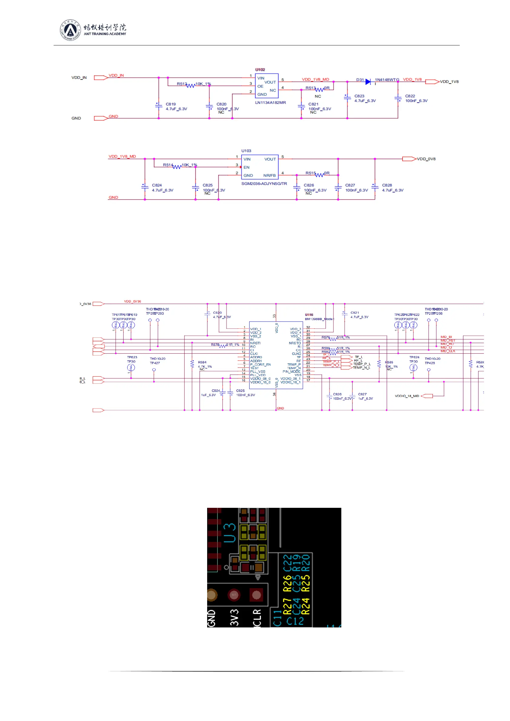
Figure 5-11
Sixth step: check the chip signal output (CLK/CI/RI/BO/RST)
1. Refer to the voltage value range described by the signal trend. If the measurement encounters a large deviation of the voltage value, it
can be compared with the measured value of the adjacent group to determine.
PS: If the hashboard is not powered or powered off according to the test sequence, causing R8, R9, U1, and U2 to burn out, the chip will
report 0;
Figure 5-12
2. When the EEPROM NG is displayed on the LCD screen of the hashboard tester, check whether the welding of U5 is normal;
3. If the PICsensorNG is displayed on the LCD screen of the hashboard tester and the test read temperature is abnormal, then follow the
steps below to troubleshoot:
A) Check whether the 4 resistors of R24~R27 are welding abnormally, and check whether the welding of PIN2, 3 of U3 is normal;
Figure 5-13