S19 Maintenance Guide
12
b) If one chip can be found in step a), it indicates that the first chip and the previous circuit are good. Use a similar method to check the
subsequent chips. For example, short-circuit the 1V8 test point and the RO test point between the 38th and 39th chips. If the log can find
38 chips, the first 38 chips have no problem; if you still find 0 chips, check the 1V8 first; if it's normal, it means that there is a problem
with the chip after 38. Continue to investigate with dichotomy until the problematic chip is found. Assuming that there is a problem with
the Nth chip, when the 1V8 and RO between the N-1th and Nth chips are short-circuited, N-1 chips can be found, but when the 1V8 and
RO between the Nth and N+1th chips are short circuited, the entire chip cannot be found.
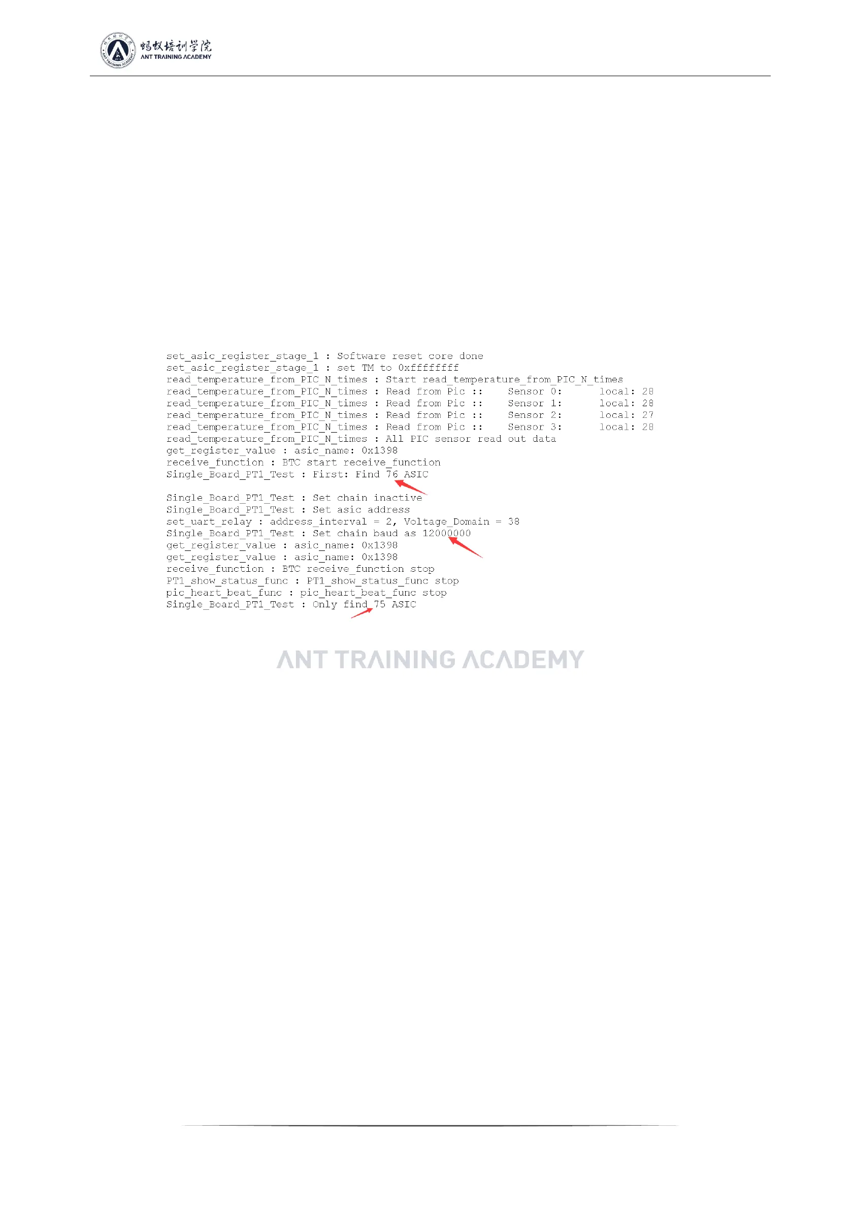
c) LCD display ASIC75: (Reporting 75), it means that the hashboard can detect 76 chips at 115200 baud rate, but only 75 chips are found
at 12M baud rate, and one chip could not find at 12M baud rate;
Repair method: Using the dichotomy method, short-circuit the 1V8 test point and the RO test point between the 38th and 39th chips
through the short-circuit probe. If the log can find 38 chips, there is no problem with the first 38 chips; if short-circuiting 47 chips, but the
log reports 46, it indicates that the 47th chip cannot be detected, and there is no problem with the visual inspection. Generally, the 47th
chip shall be replaced;
Figure 5-15
d) LCD display ASICNG: (X, a certain chip is fixed), there are two situations:
d-1) The first case: the test time is basically the same as the good board (usually the value of X will not change each time you test) (test
time refers to the time from when the start test button is pressed to the result of ASICNG: (X) displayed on the LCD). This situation is
likely to be caused by the abnormal resistance welding of the front and rear CLK, CI, and BO of the Xth chip, so users shall focus on these
6 resistors. The small probability is due to X-1, X, X+1, that is, among the three chips, the following pins abnormal welding conditions of
the chip occur:
 Loading...