03/13/2019 IN-0031_G 7 OF 8
FRAME AND
RACEWAY
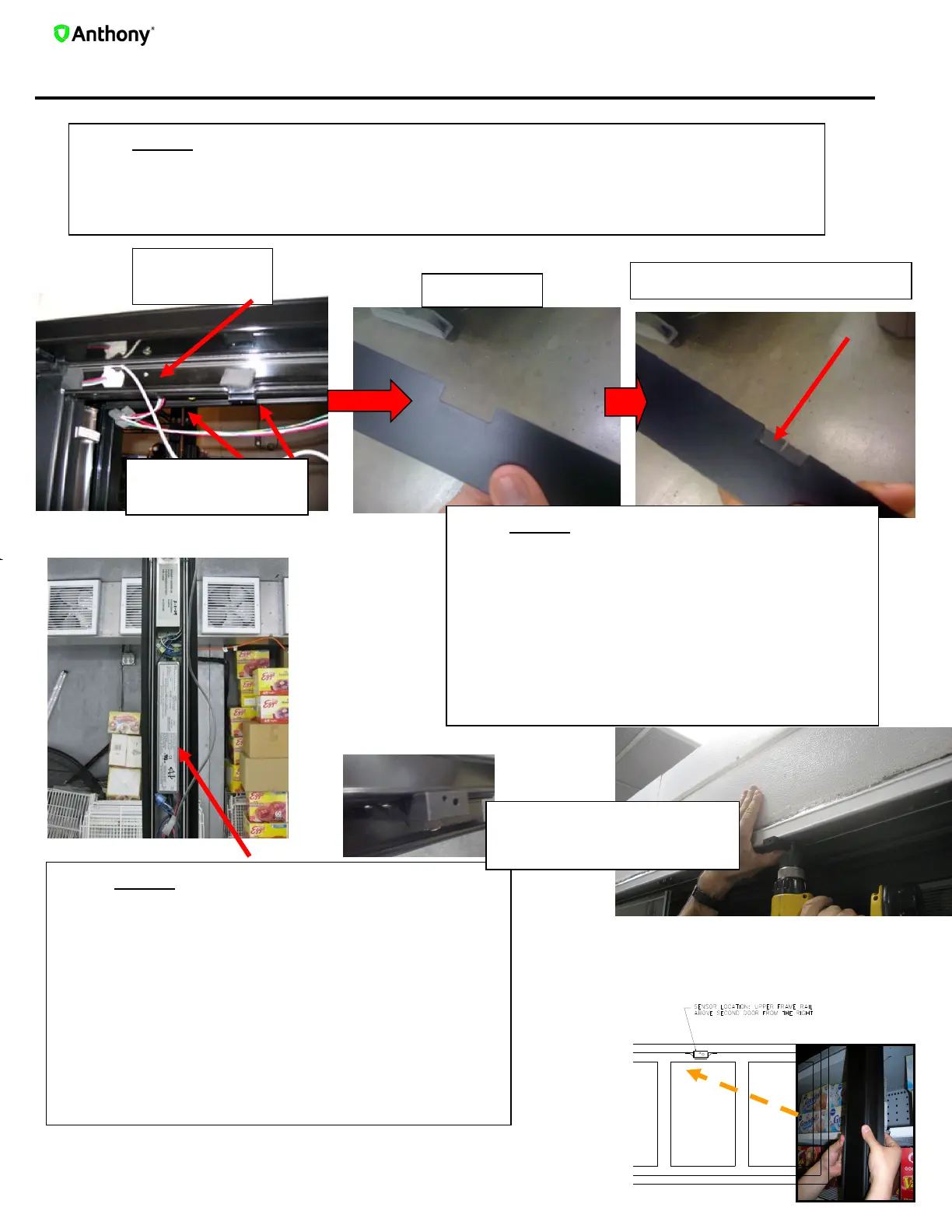
4.Standard Frame & Sensor Preparation
STEP 1
Begin wiring the smart controller following the wiring schematic on page 5.
The sensor cable must travel from the center mullion to the top of the channel
shown below .
STEP 2
Cut a ¼” X 1” rectangular cut on the
contact plate to allow for passage of the
sensor cable.
Apply a ¾” X 2 ¼” piece of seal foam with
a cut slit for wire placement on the contact
plate to prevent air intake/outtake.
Insert the sensor cable into the cutout and
replace the sealing plate to the frame.
STEP 3
Push the excess sensor cable back through
the channel, reducing the slack.
Seat the sensor (see figure for location) until
flush to the frame flange, pushing it as far
back as possible.
Using self-drilling screws, mount the sensor
housing to the inner frame of the door system.
Reinstall the sealing plates.
CUT OUT
HEATER CABLE
AND WIRES
SEAL FOAM WITH SLIT
SENSOR LOCATION: UPPER
FRAME RAIL ABOVE SECOND
DOOR FROM THE RIGHT


 To Next Page