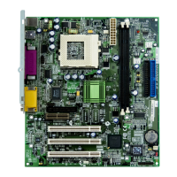
Connector Pin1 Pin2 Pin3 Pin4
CD-IN
Left GND GND Right
MODEM-CN
Mono In GND GND Mic Out
AUX-IN
Left GND GND Right
12. Connecting CD / MODEM / AUX Connector
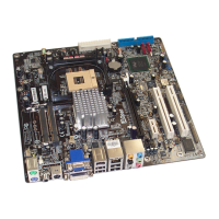
13. Front Audio
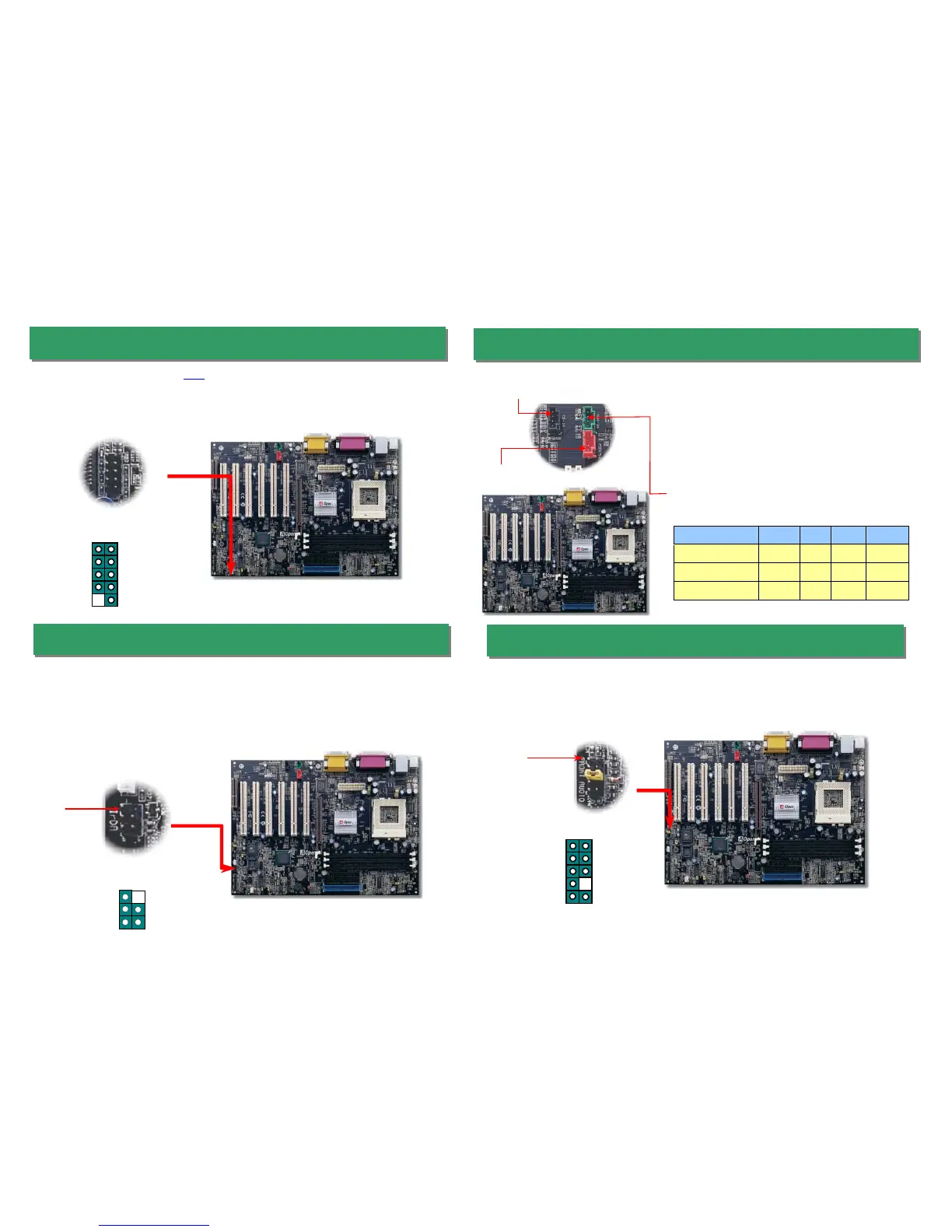
11. Connect IrDA Connector
The IrDA connector can be configured to support wireless infrared module, with this
module and application software such as Laplink or Windows 95 Direct Cable
Connection, the user can transfer files to or from laptops, notebooks, PDA devices and
printers. This connector supports HPSIR (115.2Kbps, 2 meters) and ASK-IR (56Kbps).
Install the infrared module onto the IrDA connector and enable the infrared function
from BIOS Setup, UART mode select, make sure to have the correct orientation when
you plug in the IrDA connector.
If the housing has been designed with an audio port on the front panel, you’ll be able to
connect onboard audio to front panel through this connector. By the way, please remove
the jumper cap from the Front Audio Connector before you connect the cable. Do not
remove this yellow jumper cap if housing without an audio port on the front panel.
The CD-IN connector is used to connect CD Audio
cable from CDROM or DVD drive to onboard sound.
The MODEM-CN connector is used to connect
Mono In/ Mic Out cable from internal modem card to
onboard sound circuit.
The AUX-IN connector is used to connect MPEG
KEY
GND
IR_RX
Pin 1
Pin 1
FP_MIC
NC
PHONE_R
NC
PHONE_L
GND
+5V
JS1
KEY
NC
1 2
9 10
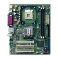
10. Support 2
nd
USB Port
This motherboard provides four USB connectors to connect USB devices, such as mouse,
keyboard, modem, printer, etc. There are two connectors on the PC99 back panel. You
can use proper cable to connect the other USB connector to the back plane or front panel
of chassis.
USB2 Connector
+5V
SBD2-
SBD2+
GND
KEY
+5V
SBD3-
SBD3+
GND
NC
1 2