AOpen reserves the right to revise all the
specifications and information contained in this
document, which are subject to change without notice.
Part No.: 49.MA601.A110
Doc. No.: MP965DR-EG-E0705C
Specification TableSpecification Table
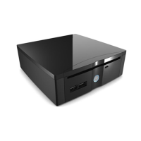
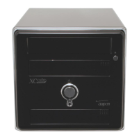
MP965-DRProduct Name
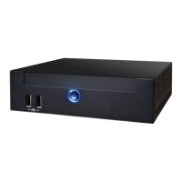
Size
(mm/inch)
165mm (W) x 165mm (D) x 50mm (H)
6.49 (W) x 6.49 (D) x 1.96 (H) (inch)
Weight (N.W.)
1.46 kg
2.4 pound
Volume
1.36 L
CPU
Socket P
Support Intel
®
Core™ Extreme (Merom)
Intel
®
Core™ 2 Duo (Merom)
Intel
®
Celeron® inside (Merom)
FSB 800/533MHz
Chipset
Intel
®
965GM
Intel
®
ICH8M
Memory
Dual Channel DDRII 667/533MHz
Graphics
Intel GMA 3100
Integrated Chrontel DVI Chip
DVI / VGA
Port
DVI Port
VGA Port
(by DVI to DVI+VGA Y-Cable or DVI to VGA Converter)
Multi-TV Out
Port
S-Video Port
Y/Pb/Pr Port (by S-Video to Y/Pb/Pr Cable)
HDMI
Interface
HDMI interface
(by Converter)
Expansion Slot
mini Card Slot x 2
Storage
Integrated Serial ATA Controller
LAN
Intel PCI Express Gigabit LAN Chip
USB 2.0
Integrated in Chipset, USB 2.0 x 4 Port
(Front Panel x 2, Rear Panel x 2)
IEEE 1394
Agere 1394 Control Chip
Audio
High Definition Audio on Board
5.1 Channel
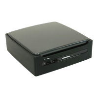
Chassis
2.5" SATA HDD Bay x 1
Slim in ODD Bay x 1
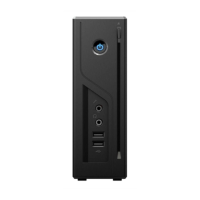
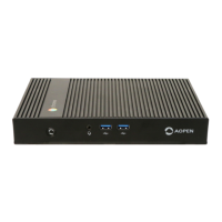
Front Panel
USB 2.0 x 2 Port
Power Button x 1
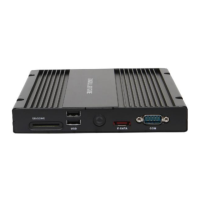
Rear Panel
Mainboard OverviewMainboard Overview
Intel PCIe Gigabit
LAN Chip
Realtek HD Audio Codec
Chrontel 7307
Socket P Support
Intel Core 2 Duo /
Celeron Processor
Intel GM965 Chipset
CPUFAN Connector
Front Panel Connector
Dual Channel
DDRII 667/533
SODIMM x 2
USB2.0 port x 1
USB2.0 port x 2
BIOS
DIO port x 1
SATA Board
Connector
mini Card Slot
Back Panel
Accessories ListAccessories List
Screw of
SATA Card
(2pcs)
S-Video to
YPbPr Cable
MPI-SATA
Card
90W DC
Adapter
S/PDIF
Converter
by Territory
Power Cord
User's Guide Driver CD
EIG
Power DVD
V.7.0
Option
CD & DVD
7.7 Maker
Option
Screw of HDD
(4pcs)
Remote
Control
DVI to HDMI
Adapter
DVI to DVI+
VGA Cable
DVI to VGA
Converter
MP965-DR only MP965-D only
Battery
DVI Port USB 2.0 Ports
S-Video Out Port RJ45 LAN Jack
DC Jack
Upgrade for TV
Tuner Antenna
Security Lock
IEEE 1394 Port
Line in
(S/PDIF out)
Line Out
Microphone
Upgrade for Wireless
802.11 Antenna
Easy Installation Guide
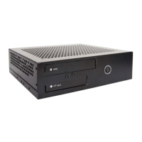
MP965-D
DDRII SODIMM slot x 2
Max. Size: 4GB
None
CPU Thermal
AOpen Proprietary Super quiet FAN (Below 27db)
Remote
Control
None
Vista Certificate RC6
Remote Control
Power
90-watt AC-DC Adapter (19V, 4.74A)
Input Voltage
AC 100 ~ 240V
Support OS
Windows XP / Windows MCE / Windows Vista Premium
Optional
Super Multi ODD / Combo ODD
TV Tuner mini Card Kit
Wireless LAN mini Card kit
Buletooth Module kit
Security Lock x 1, DC Jack x 1
DVI Port x 1, S-Video Out Port x 1
RJ45 LAN Jack x 1, IEEE 1394 Port x 1, USB2.0 Port x 2
Line in x 1 (or S/PDIF Out x 1)
Line Out x 1, Microphone In x 1
Upgrade for wireless Antenna Port x 1
Upgrade for TV Tuner Antenna Port x 1
HDD indicator
mini Card Slot
LPC port x 1
Intel ICH8M Chipset
Agere 1394
Control Chip
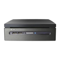
MP965-DR only MP965-DR only
USB 2.0 Ports
DVD Eject Button
Power Button
Power indicator
Optical Device Drive
IR indicator (MP965-DR only)
1. Disassemble the Top Cover carefully to avoid scratching the Top Cover.
2. Use the "+Shape" screwdriver to detach the sheet metal screws (4pcs).
3. Disassemble the product to two modules (Upper module and
Chassis module).
Disassembly mini PCDisassembly mini PC
Rear
Top
Cover
Front
1 3
24
Top
Cover
(Upper module) (Chassis module)
Note:
There is one cable connected to
board. Please keep it connected.
If you remove it by accident,
please connect it again.
5. Use the "- shape" screwdriver to turn CPU socket screw toward
the Lock mark. (Clockwise direction)
6. Fit the CPU Cooler into their respective holes of the mainboard
and use the "+ shape" screwdriver to tighten screw 1-2-3-4-5-6.
make sure the CPU Cooler is fastened to the mainboard evenly.
1
3
2
4
5
6
Lock
Note: When screw the socket. You will hear a slight sound
"Dock". That means you already installed CPU successfully.
1. Take the chassis Module. Detach 6 screws of the CPU Cooler by
the "+Shape" screwdriver. The sequence of operationis
1-2-3-4-5-6.
2. Move over the CPU Cooler carefully. Avoid damaging the
component of the mainboard.
3. Use the "- Shape" screwdriver to turn CPU socket screw toward
the unlock mark. (Anticlockwise direction)
Note: If you do not match the CPU Socket Pin1 and CPU Golden
arrow well, you may damage the CPU.
4. Remove existing CPU, then install new CPU.
Locate Pin 1 in the socket and look for a golden arrow on the
CPU upper interface. Match Pin 1 and golden arrow. Then
insert the CPU into the socket.
Upgrade / Installing CPUUpgrade / Installing CPU
1
3
2
4
5
6
Unlock
Socket Pin1Golden Arrow
UnlockLock
Socket Screw Socket Pin1
CPU Frequency TableCPU Frequency Table
Processor Number Architecture Clock Speed Front Side Bus L2 Cache
Note:
With CPU speed changing rapidly, there might be faster CPU on
the market by the time you received this installation guide.
This table is kindly for your references only.
Core 2 Duo T7800 65nm 2.60 GHz 800 MHz 4MB
Core 2 Duo T7700 65nm 2.40 GHz 800 MHz 4MB
* GM965 support front side BUS 533MHz / 800MHz.
This socket supports FCPGA6 package CPU (Socket P), which is the
latest Merom Core 2 Duo (Santa Rosa) package developed by Intel.
Other forms of CPU package are impossible to be fitted in.
Core 2 Duo T7500 65nm 2.20 GHz 800 MHz 4MB
Core 2 Duo T7300 65nm 2.00 GHz 800 MHz 4MB
Core 2 Duo T7250 65nm 2.00 GHz 800 MHz 2MB
Core 2 Duo T7100 65nm 1.80 GHz 800 MHz 2MB
Celeron 550 65nm 2.00 GHz 533 MHz 1MB
Celeron 540 65nm 1.86 GHz 533 MHz 1MB
Celeron 530 65nm 1.73 GHz 533 MHz 1MB
Merom