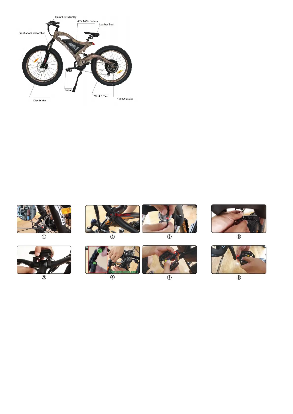
Frame 6061 aluminum alloy Battery 48V 14AH Li-ion battery SAMSUNG
Motor 1500W rear motor Controller 48V 30A
Charge Time 4-6 hours Max Speed 50 km/h
Range Distance 25-40 km Brake F/R disc brake
Light With F/R light Display Color LCD display
Fork Al alloy suspension fork Tire 26×4.0
Derailleur Outer 7-speed SHIMANO
Packing
Size
163 X 28 X 82 CM
Safety Notice
To Ensure Your Safety, Make the Following Functional Checks Before Driving:
1. Test brake system, throttle, and power system.
2. Tire pressure should be at 30 psi.
3. Check front wheel lug-nuts, securely tighten before every ride.
4. Battery charge level- found on side of the battery
5. Braking system adjustment and free operation.
Installation instructions
1. Open your package.
2. Take out the toolbox.
3. Take out the bicycle from the package and put it on a soft surface to avoid scratches. Cut the tie that secures the front wheel to the side
4. Remove the protective foam.
5. Open the accessory kit and remove the tool kit
6. Invert the bicycle.
7. Remove the large fixing bolt on the front fork.
8. Put the front wheel on the front fork and place the disc brake pad on the front wheel in the middle of the disc brake caliper( Figure 1).
9. Use the supplied 15mm flat tool to tighten the two bolts.
10. Tie the key to the handlebar clamp, cut the zipper, and then use the Allen wrench in the tool kit to remove the clamp.
11. Place the handlebar in the middle position (Figure 2), install the rod clamp, and tighten the screws with the included Allen wrench.
12. 1nstall the LCD display on the handlebar (Figure 3), tighten the screws, and connect the green connecting wire (Figure 4)
13. Grasp the bicycle light and unscrew the lens. Then, remove the plastic insulator, re-tighten the lens, and then connect the red cable (Figure 5), and connect the bicycle light to the
screw above the front fork (Figure 6).
14. 1nstall the pedal. The right pedal rotates clockwise (Figure 7), and the left pedal rotates counterclockwise (Figure 8). NOTE: Pedal mark “L” means left and “R” means right.
15. Vertical bicycle
16. Push the seat into the column, fix it in the desired position, tighten the screws, and then fix it.
17. 1nstallation is complete. When connecting meters, headlights, brake circuit breakers, handlebars, etc., please align them and do not install them violently(Figure 4).
Battery Installation & Maintenance
1. Please check the situation of the lock core before installation, Step 2 and Step 3 for details.