Do you have a question about the Apelco XCD-550 and is the answer not in the manual?
Crucial safety and operational disclaimer regarding device accuracy and user responsibility.
Contact details for Apelco support in the US and Europe for product assistance.
General introduction to the XCD 550 as an advanced LCD graph recorder/plotter.
List of all items included in the XCD 550 carton for initial setup.
Catalog of optional accessories that can enhance the XCD 550's functionality.
Technical details of the LCD screen, including dimensions, resolution, and backlight.
Lists the available operating display modes: Standard FF, Plot, A-Scope, and Nav/Temp.
Specifies the types of transducers compatible with the unit: Triducer, Transom, Thru-Hull.
States the operating frequency of the transducer, which is 200 kHz.
Indicates the peak-to-peak transmission power of the unit, rated at 800 watts.
Specifies the rate at which the unit transmits sound pulses, approximately 400 pulses/min.
Details the pulse width options for transmission, .2 & .5 ms based on range.
Covers setting range scales, chart speeds, and alarm configurations.
Details gain adjustment, depth markers, whiteline, and digital depth display.
Covers fixed STC, minimum depth capabilities, and interference rejection.
Defines plot presentation and lists available map scales for plotting.
Covers ship track recording, memory intervals, and event mark functionality.
Details displaying external waypoints and resetting the plot view.
Specifies temperature range and allows selection of ship speed units.
Lists the calibration options available for speed, temperature, and magnetic variation.
Details how to calibrate ship speed and temperature readings.
Covers magnetic variation input and power supply specifications.
Describes cabinet material, control panel, and LCD window specifications.
Lists in/out connections, overall unit dimensions, and mounting hardware.
Details the power cable length and fuse, 6 ft. with in-line fuse.
Guidance on selecting an optimal mounting location for the main unit, considering viewing angle and environment.
General instructions for installing transducers, emphasizing careful handling of the delicate instrument.
Step-by-step guide for assembling the transducer bracket components.
Procedures for attaching the assembled bracket to the hull, including screw location guidance.
Instructions for adjusting the bracket's release force for optimal protection against grounding.
Critical warning about not over-tightening the release adjustment screw to prevent locking.
Warnings about installing bronze housings in metal hulls and cored hull structures.
Guidance on choosing the best location for thru-hull transducers on various boat types.
Recommendations for mounting transducers on displacement hull power boats.
Advice for mounting transducers on planing powerboat hulls, considering speed.
Warnings against mounting transducers behind obstructions that cause turbulence.
Guidance for mounting transducers on I/O and inboard vessels, avoiding propeller turbulence.
Advice on inspecting hull paint for erosion and ensuring internal access for installation.
Lists necessary tools and materials for transducer installation.
Explains the use and importance of fairing blocks for angled hull installations.
Warning that connector removal or cable splicing voids the transducer warranty.
Details power requirements, connection to 12 VDC systems, and recommended circuit protection.
Explains connecting to Loran or GPS for position data using NMEA formats.
Step-by-step guide for assembling the connector plug for data input.
Instructions for connecting an external buzzer for audible alarms.
Describes how echo sounders work by transmitting ultrasonic waves and interpreting returning echoes.
Explains how different bottom types affect echo returns and display appearance.
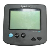
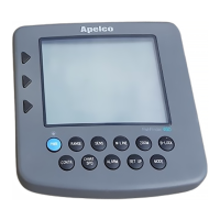
Identifies each key on the control panel and its primary purpose.
Detailed procedure for turning the unit on and off using the dual-labeled keys.
Explains how to use the DIM key to control the LCD backlighting.
Guide to adjusting the LCD contrast for optimal viewing under different lighting conditions.
Instructions for manually setting the depth range scale or using Auto Range.
Important note stating Shallow and Deep alarms are inactive when Fish Alarm is used.
How to store and retrieve event marks (fishing spots) using the EVENT key.
Instructions for resetting the trip log data using the ZOOM and ALARM keys.
How to activate and use the built-in simulator for practicing operations.
Recommends Auto Range and Auto Gain for depth tracking in NAV mode.
Covers panel operations for the NAV/TEMP mode.
How to adjust the temperature graph scale using specific keys.
Procedure for setting shallow and deep alarms in NAV/TEMP mode.
How to select a new event to steer to, with notes on Nav-Aid waypoints.
Options for selecting units for Depth, Speed, and Temperature.
Procedures for calibrating speed and temperature readings.
How to input magnetic variation data for accurate bearings.
Choosing navigation data display: Lat/Long, TD's, or BRG/DTG.
Procedure to select depth units (FT, FM, M) using the GO TO key.
Procedure to select temperature units (°F or °C) using the ZOOM key.
Procedure to select speed units (KTS, M/H, KM) using the ALARM key.
How to calibrate temperature readings using GO TO or ZOOM keys.
How to calibrate speed readings using ALARM or RANGE keys.
Guide to inputting magnetic variation for accurate bearings relative to True North.
Notes on operating the Fishfinder section within the Plot/Fishfinder mode.
How to choose between six plot scales (2-100 NM) using the UP/DOWN keys.
How to re-center the ship's position on the plot display using the GO TO and ZOOM keys.
How to mark and store event locations on the plot screen, with notes on memory capacity.
Instructions for obtaining bearing and distance to a selected event or waypoint.
How to clear track lines from the plot screen to reduce clutter.
Accessing special functions for plot mode operations via the SF key.
How to select an internal event or external waypoint for navigation.
Storing incoming waypoint data from a Nav-Aid into the unit's event memory.
Procedure for performing a master reset to erase all memorized data.
| Display | Color LCD |
|---|---|
| Power Output | 1500 W |
| Transducer | Included |
| GPS | No |
| Water Temperature Sensor | Yes |
| Battery | 12 VDC |
| Display Size | 5 inches |
| Transducer Frequency | 50/200 kHz |
| Sonar Frequency | 50/200 kHz |