Do you have a question about the API 527 and is the answer not in the manual?
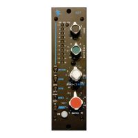
Sets the output level of the 527 with a continuously variable 31 position detented control.
Sets the compression start level, variable from +10dBu to -20dBu with a detented rotary pot.
Sets the input vs. output level ratio for signals exceeding threshold, from 1:1 to infinity.
10 LED meter indicates compression amount, with increments from -1.5dB to -23dB.
Indicates the 527's output level in VU, with increments from +3dB to -20dB.
Illuminates at +27 dBu to indicate clipping.
Activates DC control voltage summing for stereo/multichannel processing with other 527 units.
Explains the unique sum-linking behavior where all units' controls affect each other.
RMS detector receives signal after VCA, yielding smoother, softer sound.
RMS detector receives signal before VCA, yielding aggressive, harder sound.
Provides a rounded response curve for gradual, transparent compression onset.
Provides a sharp response curve for immediate, aggressive compression onset.
Adds a filter before the RMS detector to decrease low-frequency reaction, increasing punch.
Illustrates the filter's effect on frequency response, boosting high frequencies relative to lows.
Inserts or removes the 527 from the audio path via a relay bypass when set to IN or OUT.
Details impedance, levels, attack/release times, ratios, and threshold ranges.
Covers LED scales, frequency response, THD, signal-to-noise, and power requirements.
Provides dimensions, weight, and compatibility with 500 Series racks and consoles.
| Bypass | Yes |
|---|---|
| Form Factor | 500 Series |
| Type | Compressor |
| Channels | 1 |
| Controls | Threshold, Ratio, Attack, Release |
| Metering | Gain Reduction |