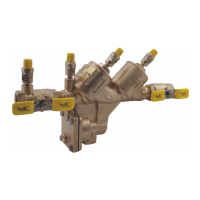
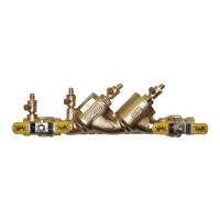
The Apollo Valves Reduced Pressure Principle (RP) Backflow Preventer, models RP4A and RPLF4A, is a critical device designed to protect potable water supplies from contamination due to backpressure or backsiphonage. This manual provides comprehensive instructions for its installation, operation, and maintenance, covering sizes from 1/2" to 2".
Function Description:
The core function of the RP backflow preventer is to create a zone of lower pressure between two independently acting check valves and a hydraulically dependent, mechanically independent pressure differential relief valve. This design ensures that if a backflow condition occurs, the contaminated water cannot enter the potable water supply.
The device operates on a differential pressure principle. The first check valve is engineered to maintain a minimum pressure differential of 5 psi across itself during normal operation, while the second check valve maintains a minimum of 1 psi. The relief valve, strategically located in the zone between the two check valves, is designed to open and discharge water to atmosphere if the pressure in the zone approaches or becomes equal to the inlet pressure. This action maintains the pressure in the "zone" at least 2 psi less than the inlet pressure, effectively preventing backflow. During normal operation, supply pressure on the upstream side of the first check valve acts against a diaphragm to keep the relief valve closed. A minimum supply pressure of 20 psig is typically required for the relief valve to fully shut and both check valves to open.
The assembly includes two resilient seated shut-off valves, one upstream and one downstream, to isolate the device for testing and maintenance. Four test cocks are integrated into the design, allowing for accurate field testing of the check valves and relief valve to ensure proper operation and compliance with regulatory standards.
Important Technical Specifications:
- Sizes: Available for pipe sizes ranging from 1/2" to 2".
- Check Valve Differential Pressure:
- First check valve: Designed to maintain a minimum of 5 psi across the valve.
- Second check valve: Designed to maintain a minimum of 1 psi across the valve during normal operation.
- Relief Valve Operation: Operates on a differential pressure principle, opening to maintain the zone pressure at least 2 psi less than the inlet pressure during backpressure conditions.
- Minimum Supply Pressure: A minimum supply pressure of 20 psig is generally required for the relief valve to fully close and both check valves to open.
- Components:
- Two independently acting, spring-loaded check valves.
- One hydraulically dependent, mechanically independent pressure differential relief valve.
- Two resilient seated shut-off valves (upstream and downstream).
- Four test cocks (#1, #2, #3, #4) for diagnostic testing.
- Materials: Manufactured in the USA by CONBRaCo Industries, implying adherence to quality manufacturing standards. The manual also references specific part numbers for various components, including rubber kits and complete kits, which suggests the use of durable and replaceable materials.
Usage Features:
- Backflow Prevention: Provides robust protection against both backpressure and backsiphonage, making it suitable for a wide range of applications where cross-connection control is critical.
- Flowing Condition: In a flowing condition, the device allows water to pass through while maintaining the necessary pressure differentials across the check valves. For example, with an inlet pressure of 80 PSIG, the zone pressure might be 73 PSIG, and the downstream pressure 71 PSIG, indicating proper pressure drops.
- No Flow Condition: In a no-flow condition, the device maintains static pressure. For instance, with an inlet pressure of 80 PSIG, the zone pressure might be 75 PSIG, and the downstream pressure 74 PSIG, demonstrating the check valves holding pressure.
- Installation Requirements:
- Accessibility: Must be installed in an accessible location to facilitate periodic field testing and maintenance.
- Drainage: Requires adequate drainage for relief valve discharge, as the device should never be submerged in standing water.
- Orientation: Must be installed in the horizontal position.
- Clearance: Sufficient clearance between the lowest portion of the device and flood grade or floor is necessary for ease of maintenance.
- Flushing: Upstream piping must be thoroughly flushed to remove foreign matter prior to installation.
- Pressurization: After installation, and with the downstream shut-off valve closed, the device must be pressurized, and all air bled through test cock #4 before opening the downstream shut-off valve.
- Testing Procedures: The manual outlines a detailed 3-valve test kit procedure, although it notes that local water purveyor requirements may vary. This includes specific tests for:
- Check valve #2 against backpressure (Test No. 1).
- Shut-off valve #2 for tightness (Test No. 2).
- Check valve #1 for tightness (Test No. 3).
- Differential Pressure Relief Valve operation (Test No. 4).
- Differential pressure test on check valve #2 (Test No. 5).
These procedures ensure the device is functioning correctly and meeting performance standards.
Maintenance Features:
- Troubleshooting Guide: A comprehensive troubleshooting guide helps identify and resolve common issues such as continuous relief valve discharge, failure of check valves to hold pressure, or low-pressure differentials. This guide links specific symptoms (e.g., relief valve continuously discharges) to potential causes (e.g., fouled check valve, damaged diaphragm) and provides corrective actions (e.g., inspect and clean, replace diaphragm, eliminate pressure fluctuations).
- Disassembly and Assembly Instructions: Detailed step-by-step instructions are provided for disassembling and assembling various components, including:
- Check Valves (Disassembly and Assembly of Check Valve Poppet and Check Valve).
- Relief Valve (Disassembly and Assembly).
These instructions cover tasks like removing caps, springs, diaphragms, and O-rings, and emphasize proper reassembly techniques, including the use of Apollo lubricant (DOW® 111 or equivalent) on O-rings.
- Repair Kits: The manual lists various repair kits available for different components and sizes, facilitating easy replacement of worn or damaged parts. These include:
- Check Module Rubber Kit (universal for standard & lead-free valves), containing seat discs, check module O-rings, and cap O-rings.
- RP First Check Complete Kit (universal for standard & lead-free valves), including check module S-Assy, check module O-ring, and cap O-ring.
- RP Second Check Complete Kit (universal for standard & lead-free valves), similar to the first check kit but for the second check module.
- RP Relief Valve Rubber Kit (universal for standard & lead-free valves), containing RV diaphragm, RV bushing face O-ring, RV seat O-ring, RV stem O-ring, and RV seat disc.
- Inlet and Outlet Shut-Off Valves: Separate part numbers are provided for various inlet and outlet shut-off valve configurations (NPT, Union Ball Valve, standard handle, locking lever handle) across different sizes, allowing for specific component replacement.
- Replacement Handles: Information on replacement handles for ball valve shut-off valves (T2 & T4 options) is also included, offering flexibility for maintenance and upgrades.
- Warranty: The product comes with a 5-year warranty, indicating manufacturer confidence in its durability and performance.
Overall, the Apollo Valves RP Backflow Preventer is a well-documented and robust solution for potable water protection, designed for ease of installation, reliable operation, and straightforward maintenance.