25 AIM-4SL Hardware Manual
© 2011 Apollo Security Inc.
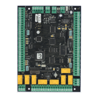
Strike
+
_
Strike Power
May Be Same As Reader
if 12 or 24 VDC
Install Supressor at Strike
(see above text)
+
_
Common
"C"
Normally Open
"NO"
Figure 3.7.3.1 Strike Wiring Diagram- Fail Secure.
A wiring example for Fail Secure wiring. Refer to
Table 2.1 for exact locations of strike relay connections for the AIM-4SL.
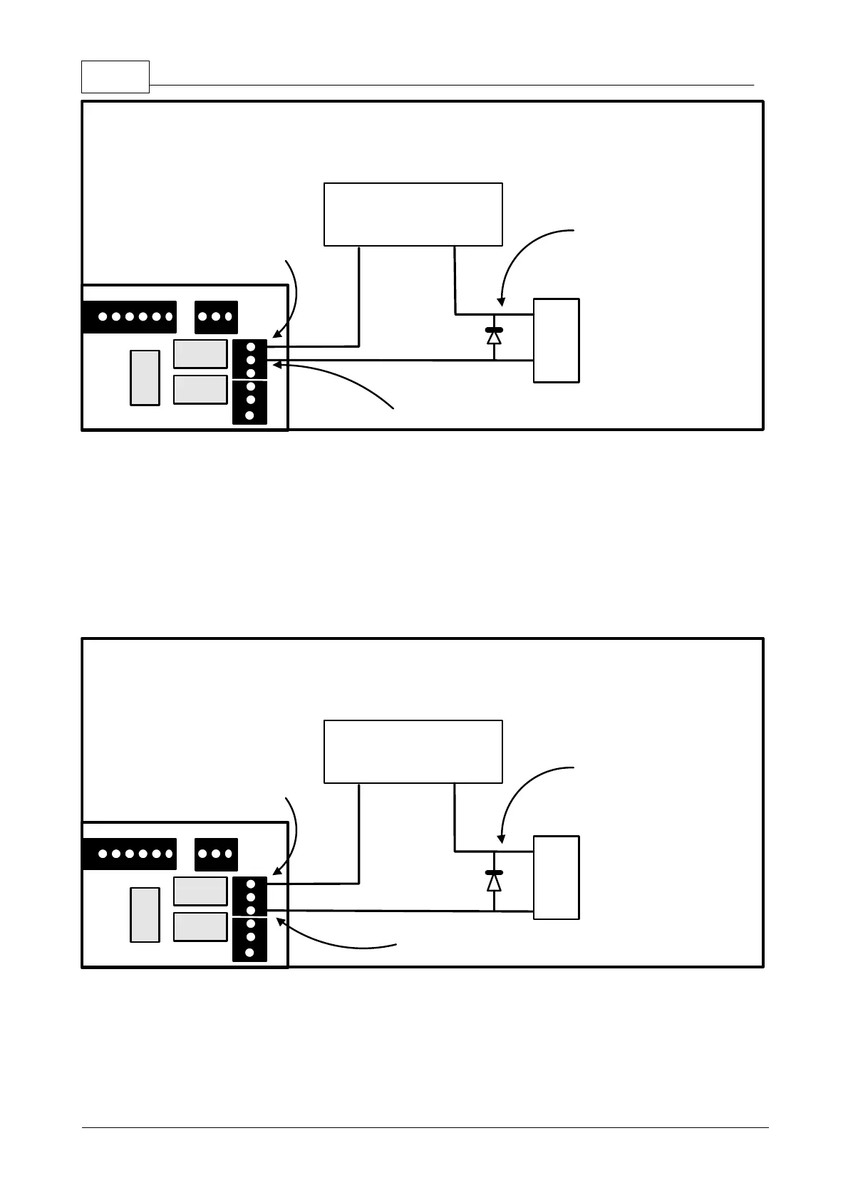
The diagram below illustrates connection of a DC powered, Fail-Safe, door strike. This type of strike requires
power to hold the door closed. The power will be supplied through the normally closed (NC) relay contact of
the strike relay. Power will be provided to the strike until the reader activates the internal relay. The reader
will activate the relay as a result of a valid access request (card swipe, card swipe plus valid PIN, valid PIN
entry only, etc.). The reader will also permanently activate the strike relay if commanded by the host software
to be “unlocked”. The reader may also be configured to activate the relay if the exit pushbutton is depressed.
Some software systems may allow configuration of this feature (activate strike relay on exit pushbutton) and
others may not.
Strike
+
_
Strike Power
May Be Same As Reader
if 12 or 24 VDC
Install Supressor at Strike
(see above text)
+
_
Common
"C"
Normally Closed
"NC"
Figure 3.7.3.2 Strike Wiring Diagram - Fail Safe.
A wiring example for Fail Safe wiring. Refer to
Table 2.1 for exact locations of strike relay connections for the AIM-4SL.