20System Wiring
© 2011 Apollo Security Inc.
Brown LED
Red +5 VDC
Green Data 0
White Data 1
Yellow Buzzer
Orange LED
Black Ground
Yellow LED (If used)
Shield
READER 3 CONNECTION
Door Contact Switch
(normally closed)
Exit Push Button
(normally open)
Auxilliary Input--Sensor
(normally open)
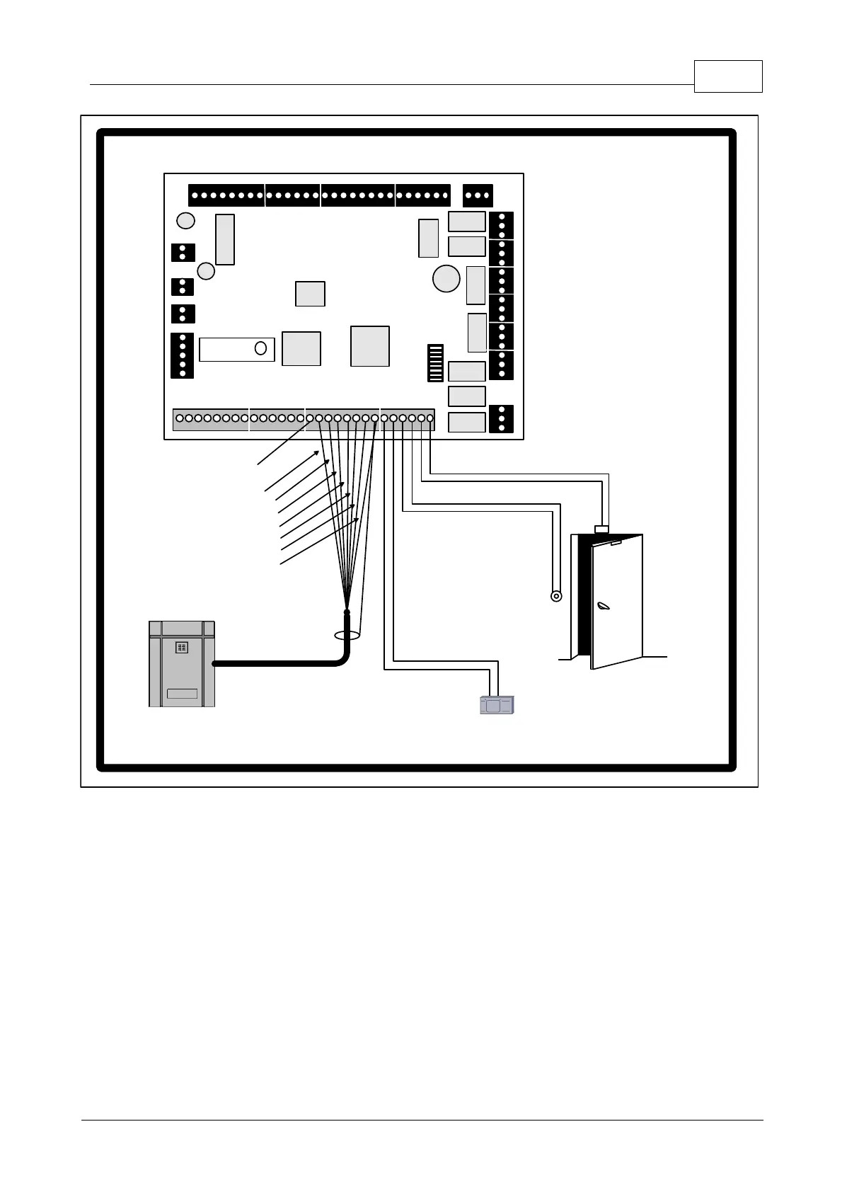
Figure 3.5 AIM-4SL Card Reader and Input Wiring.
The AIM-4SL supports up to four card readers
which are connected in standard configuration. For each reader connection there is a door contact input, exit
push button input and one axillary input which is displayed here connected to a motion sensor. Refer to the
Terminal Connectors table and the installation instructions for the reader that will be used for exact wiring
positions.
3.6 Reader Input Wiring
The each of the four reader inputs on the AIM-4SL has three input circuits (Door Contact, Exit Push Button
and Auxiliary Alarm 1). These inputs can be configured as UL Grade “B” (unsupervised) or UL Grade “A”
(supervised). The selection of supervised / unsupervised is made by changing DIP switch number 8. If in the
OFF position, the inputs for
all
readers are configured as unsupervised, if in the ON position
all three
inputs
are configured as supervised. It is not possible to have both unsupervised and supervised inputs at the same
time, all inputs must be in the same configuration. If the inputs are configured as unsupervised, the door