5 AIM-4SL Hardware Manual
© 2011 Apollo Security Inc.
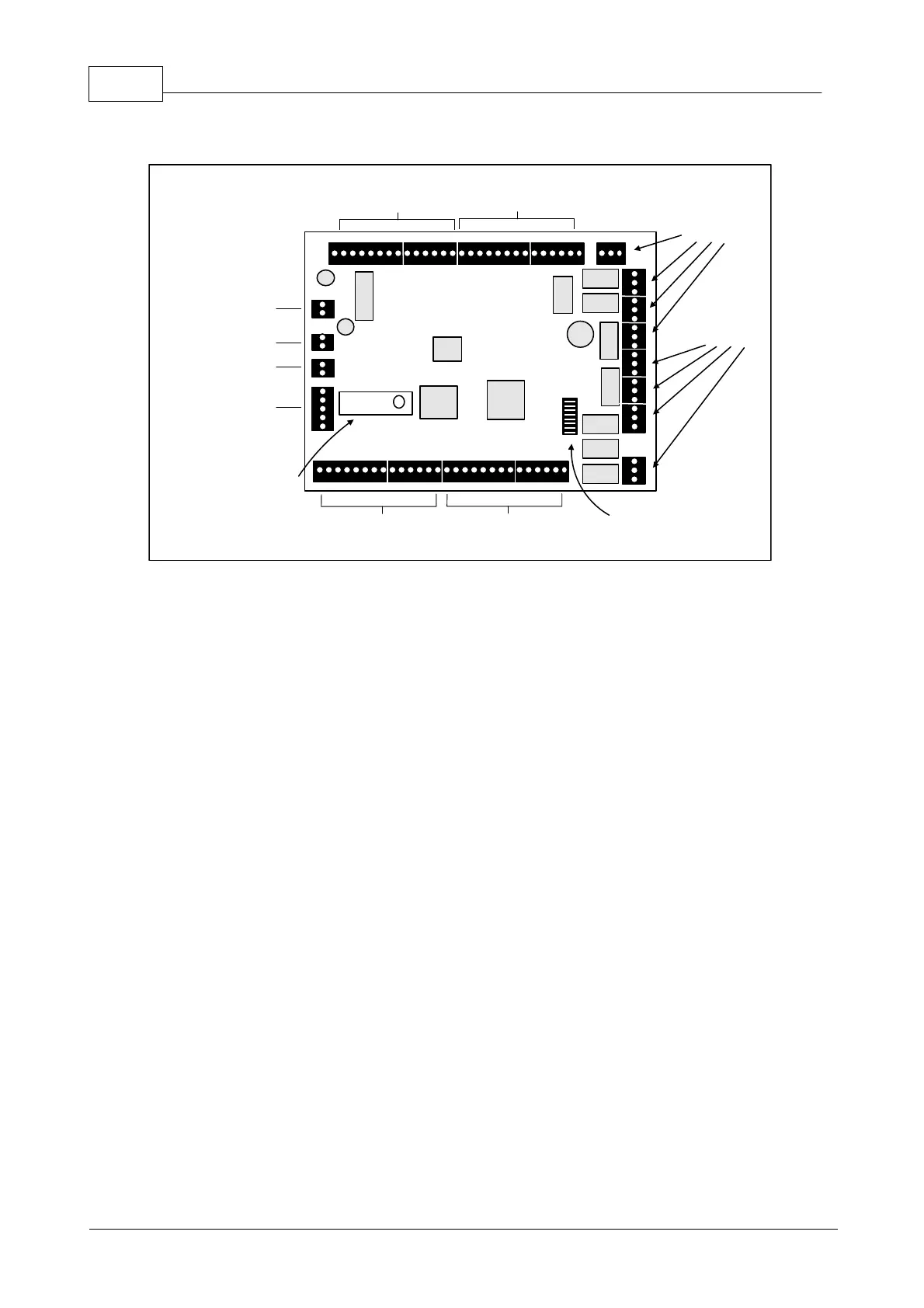
2 Hardware Layout
Reader 1
Connection
Reader 2
Connection
Reader 4
Connection
Reader 3
Connection
Power Input
Tamper Input
External Strike
Relay Loop
Serial Port
Strike Relay
Connections
1, 2, 3, 4
Auxilary Relay
Connections
1, 2, 3, 4
Removable Device
Port Driver Module
DIP Switch
Figure 2.1 AIM-4SL Diagram.
Terminal Connectors, DIP Switch, Output Relays, device port driver
connection, and other component locations are shown.
2.1 Terminal Connectors
The AIM-4SL has 9 terminal blocks for connecting power, reader and alarm inputs, and relay output
connections. The connection terminals are factory equipped with removable screw-down quick connectors
which are easily removed from the board by firmly grasping the connector and pulling away from the board.
If pliers are used to remove the connectors, they should be of the rubber-tipped type. Take care in using any
tools near the board not to damage on-board components. The proper location of the quick connectors is
outlined in white on the board.